I've got an amp on the bench thats literally driving me nuts. Initially customer brought it in with an exploded bias cap and had it running full blast which had partially cooked the board. I have replaced all the electrolytic caps and heat sensitive parts and re soldered the tube sockets to the board. The master volume is scratchy and its not the pot itself. There is constant and continuous hum in the background. New valves. I have noticed that there is an almost exact amount of DC voltage leaking through the heater rectifier section, for the preamp tubes, into the AC heaters for the power tubes. Therefore I'm getting -/+3.15vDC as well as 3.15vAC on the power tube heater pins. I have tried using different voltmeters and the result is the same.
first question is this normal?
second question...after replacing the heater rectifier cap 3300uf 10v shouldn't this problem be corrected?
third question would this leakage/problem be the cause of the hum and scratchy master?
any ideas and suggestions would be great.
first question is this normal?
second question...after replacing the heater rectifier cap 3300uf 10v shouldn't this problem be corrected?
third question would this leakage/problem be the cause of the hum and scratchy master?
any ideas and suggestions would be great.
You mean the AC supply for the power tube heaters is also rectified and sent to the preamp heaters? Then yes it is normal to measure a DC offset on the AC side, relative to ground. But you should read no DC between the AC heater legs.I have noticed that there is an almost exact amount of DC voltage leaking through the heater rectifier section, for the preamp tubes, into the AC heaters for the power tubes.
...I'm getting -/+3.15vDC as well as 3.15vAC on the power tube heater pins....
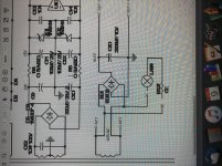
Look at the plan you posted. This is exactly what we'd expect.
The big tubes are fed with 6.0V AC. This also feeds a FWB making 6.1V DC, ground referenced, for the little tubes. This connection will put 3.05V of DC on the 6.0V AC winding. This will work fine.
I'm not wild about the ~~1V 120Hz ripple on the "DC heat". However they sometimes do OK.
This is not your scratchy pot.
Attachments
Running AC and DC heaters off the same secondary is somewhat cheapskate design, and it will give you the DC you are measuring. However, in a sense it is switched DC, because the AC heater line is only connected briefly to the DC rail every 10/8.33ms. Seems a recipe for buzz. Poor design, but probably not the source of your problems.
I have uploaded the whole schematic here:
View attachment T40.pdf
And also the voltage readings on the valves here:

Can anyone see any erratic readings or point out any thoughts on what might be the problem? Removing T3 doesn’t eliminate nor the noise nor the scratchy master volume pot
Thanks
j.
View attachment T40.pdf
And also the voltage readings on the valves here:
Can anyone see any erratic readings or point out any thoughts on what might be the problem? Removing T3 doesn’t eliminate nor the noise nor the scratchy master volume pot
Thanks
j.
Normally 'scratchy' pots are due to mechanical problems, worn track / shaft etc., or because there is some DC voltage applied to them (by poor design or by a fault).
I know nothing of the amp you refer to, so assume your 'master' is VR6?
If you are sure it is not a mechanical problem first check there is no DC on the signal line to it. Or open the signal path at JK6 and test again for 'scratchiness'. Then work from there.
I too would ignore the AC/DC heater as a fault. And ask, was the hum there from new or developed recently? Does it change with volume setting etc.. Some of these amps are not silent or supposed to be.
Apologies if you have these covered already, just not clear from the postings. Alan
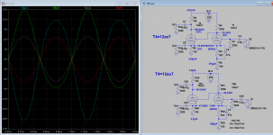
For tube T4A, which is a 12ax7, the anode and cathode current is about 63/1k~=4.2mA. This is much higher than max of 1mA. So extra current might be the cause of hum and distortion, but it might be what the designer wanted I don't know. Please check all values of resistors around these area. R55/R56 (15k) is way to low for 12ax7, could be 150k? If 150k the current is about 0.77mA (<1mA).
You probably have grid current in T4B. This will eventually make VR6 scratchy, but this could take a few years so safely outside the warranty period. Poor design to run a 12AX7 with such a low cathode-grid voltage and then directly connect it to a pot wiper. The fix is to put a coupling capacitor between the pot and the valve grid.
I agree that T4A is poorly biased. My guess is that whoever 'designed' this was not familiar with correct usage of the 12AX7. R55/56 need to be higher values so T4A runs less current. The anode voltage of T4B needs to be a bit higher so T4B will run less grid current. You could try reducing the 220k to 180k or 150k.
I agree that T4A is poorly biased. My guess is that whoever 'designed' this was not familiar with correct usage of the 12AX7. R55/56 need to be higher values so T4A runs less current. The anode voltage of T4B needs to be a bit higher so T4B will run less grid current. You could try reducing the 220k to 180k or 150k.
Ok basically got my hands on another identical amp and the hum is the same so I’m not going to fuss about that... it’s just the scratchy master volume pot that I have to resolve. I’ve taken voltage readings comparing the 2 amps and they’re very much identical even voltage readings around T4B are almost identical. I have already replaced C95 off the master volume pot but that doesn’t change anything. What else would create that scratchy noise? Would one of the opamps off the send/return jacks cause that?
I already told you: grid current damaging the pot. Replace the pot, and add a coupling capacitor to keep current away from the wiper.jimmy74 said:What else would create that scratchy noise?
- Status
- This old topic is closed. If you want to reopen this topic, contact a moderator using the "Report Post" button.
- Home
- Amplifiers
- Tubes / Valves
- DC voltage leaking into AC voltage heater rail