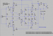
First a couple of disclaimers. This is just a quick circuit I threw together to illustrate a concept and not in any way intended to represent any real implementation. Thus the fake phase inverter simply to get split phase signal for the simulation and the use of non-optimal driver tubes and bias points. I am interested in your thoughts on the concept.
Instead of plate to plate local feedback plate to cathode feedback has been discussed as an alternative. This is usually done via a capacitively coupled feedback to the driver's cathode. What I wonder is if there is something to be gained by direct coupling it through a follower thus eliminating the feedback blocking cap. I am using a 1 meg voltage divider from the output tube plates to set a bias point for the follower on the theory that such a large resistance will not provide a significant load on the output stage. Of course I am sure that a MOSFET would be the preferred follower but I still think in tubes so that was the easiest thing for me to knock up.
Is this tres` Loco?")
Instead of plate to plate local feedback plate to cathode feedback has been discussed as an alternative. This is usually done via a capacitively coupled feedback to the driver's cathode. What I wonder is if there is something to be gained by direct coupling it through a follower thus eliminating the feedback blocking cap. I am using a 1 meg voltage divider from the output tube plates to set a bias point for the follower on the theory that such a large resistance will not provide a significant load on the output stage. Of course I am sure that a MOSFET would be the preferred follower but I still think in tubes so that was the easiest thing for me to knock up.
Is this tres` Loco?
Attachments
I can.see where it adds its own.artifacts to the loop but how does it not eliminate the cap. All the P-C FB I have seen is AC coupled? Are you suggesting just carefully selecting resistor values such that the driver's cathode remains at a reasonable level, FB ratio is appropriate, and loading of output is acceptably low? How much higher then Z(p-p) would be sufficient? 10x, 20x?

Hmmm... This does seem feasible. Wonder why I have not seen it done before.
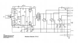
It's been done before. Western Electric did it back in the pre-war days such as Model 131A. Most WE amps from models 103 to 133 all have feedback taken from the plates, single ended and push-pull, although mostly through a cap. The model 124 being the most popular of that era. And this plate to cathode feedback scheme contributes a lot of that Western Electric sound. What's unique about 133 is that it has no blocking caps similar to your posted circuit. My friend has a pair and they sound great.
Attachments
How do you analyze a feedback scheme like this?
Please help me get my head around this. How does one analyze a feedback loop like this? that is how do you calculate the amount of gain reduction from open to closed loop or more importantly how are circuit values chosen to achieve a desired level of feedback? It seems like it should be a fairly simple relationship but I can't seem to get my head around it.
Please help me get my head around this. How does one analyze a feedback loop like this? that is how do you calculate the amount of gain reduction from open to closed loop or more importantly how are circuit values chosen to achieve a desired level of feedback? It seems like it should be a fairly simple relationship but I can't seem to get my head around it.
Attachments
The closed loop gain of a system can be expressed as a function of the open loop gain and the feedback factor:
Acl = Aol/(1+B*Aol)
where:
Acl = closed loop gain
Aol = open loop gain
B = feedback factor
There's a voltage divider relationship between R3 and R7 that sets the feedback factor. It is R7/(R3+R7). Open loop stage gains can be calculated from the plate curves or estimated using mathematical models.
You can now work backward assuming R7 is fixed, to estimate a value of R3 that will deliver a given amount of gain reduction.
Feedback is DC coupled so changing R7 affects first stage bias. You could reduce that interaction by making R7 smaller and readjusting R3 so the feedback factor is unchanged.
...How does one analyze a feedback loop like this? that is how do you calculate the amount of gain reduction....
12AX7 has gain of 50, except the 1K cathode NFB makes it 25.
6V6 with any happy power load works at gain (g-p) of about 10.
Forward gain is 25*10 or 250.
180K:500r NFB network is 360:1 ratio.
Since the NFB net ratio is larger than the forward gain, there is "hardly any" NFB at design load.
6V6 output impedance is much higher than normal load. The NFB reduces that but the Damping Factor is less than unity.
This "hardly any" NFB *may* do some good in Loudspeaker work, because driver impedance can go very high, but this also gets more voltage gain out of the 6V6, so the bass resonance may be significantly more controlled than no NFB at all.
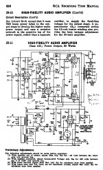
The RCA Handbook 50 Watt amplifier uses direct coupled plate to driver cathode N Fdbk (no cap). It also uses "shunt Schade" plate to grid N Fdbk, which kills the loop gain for the generally more effective plate to cathode N Fdbk. I can only surmise that RCA wanted a design that would be stable for DIY construction. (so reduced N Fdbk loop gain)
Would be interested to hear what PRR's opinion is on this odd N Fdbk combo.
There were some comments by Joe Rasmussin once about trying one or the other N Fdbk loop and some perceived difference in sound. One sounding "dark" and the other something else, can't remember. Not clear what is going on there. Which might get one to think that the designer tuned up the sound of the RCA design by selecting how much loop gain was allotted for each loop type.
Attachments
The N Fdbk to the driver cathode(s) does help linearize the driver pentode(s) V to I function, so is an improvement over -just- the "shunt Schade" plate to grid N Fdbk for sure.
But that's all part of the plate to driver cathode N Fdbk function anyway. Seems that the driver CFB would be all the more effective at linearizing the full output function if it were left alone with high loop gain (no driver plate loading from the shunt loop).
So maybe a distortion analysis might give some clue to any sonic "benefits". The residual distortion (finite loop gains) from the driver CFB loop and the Shunt Fdbk loop might have opposite 1st order curvature (2nd harmonic), so could be played off against each other for some kind of null. Maybe explaining the perceived sound difference (if any). Doesn't seem too likely one can get a more general higher harmonic cancellation, especially versus signal amplitude variation. And sure would depend on the actual tubes plugged into the amp.
One reason I'm curious, is if I were to change that 6CB6 driver to a 6EW6 for example. (higher gm, could drive a bigger tube)
Maybe they just didn't want it to oscillate easily with DIY construction. ?
Could also be a scheme to linearize the mid voltage range, but leave some softer clipping at the peaks. Dunno, would have to put the amp on a scope to see what it's doing.
Hmmm...
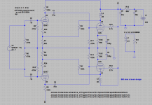
Note: I took out some extraneous stuff to make it simpler.
With this circuit (100:1 ration of feedback resistor to cathode resistor) I get open loop gain from driver grid to output tube plate of 700 and closed loop of 72 for about 18dB of degeneration.

Interestingly if I make the feedback resistor less than 111K I get a sudden switch to a 1st order rising frequency response. I believe this is because the cathode is being over driven by the feedback.
Note: I took out some extraneous stuff to make it simpler.
With this circuit (100:1 ration of feedback resistor to cathode resistor) I get open loop gain from driver grid to output tube plate of 700 and closed loop of 72 for about 18dB of degeneration.
Interestingly if I make the feedback resistor less than 111K I get a sudden switch to a 1st order rising frequency response. I believe this is because the cathode is being over driven by the feedback.
One might expect some interaction between the output Z at the output tubes plates and the leakage L of the OT, but 0.99995 coupling doesn't leave much room for that. Also would expect decreasing response at HF then I think.
Where are you measuring the freq. response? At the plates or at the final load?
Where are you measuring the freq. response? At the plates or at the final load?
The sudden change in response shows up at the output tube plate (and of course at the driver cathode and the OPT secondary). What would be a more realistic coupling figure to use?
I made a few changes that give more driver voltage swing by changing the bias on the AX7s to 1K Rk and 250k Ra. It still becomes a differentiator at the same 73:1 ratio of Rf to Rk.
I made a few changes that give more driver voltage swing by changing the bias on the AX7s to 1K Rk and 250k Ra. It still becomes a differentiator at the same 73:1 ratio of Rf to Rk.
...if I make the feedback resistor less than 111K I get a sudden switch to a 1st order rising frequency response....
I think you turn the 12AX7 OFF, due to the large DC injected under it. Then you are living on stray capacitive leakage, all treble.
Always observe your DC conditions when messing with an amp. Especially in this connection which bleeds significant DC into a low-level stage. A sim-ammeter, or a volt reading on 12AX7 plate, would show it getting starved to death.
That is pretty much what it looked like to me and what I meant by over driving the cathode. Of course the AX7 is not the best choice for this kind of circuit. I will investigate using the cap and also other driver tubes. The P-K feedback might be a nice approach for something like the 6HZ8s I just picked up off the dollar list.
- Status
- This old topic is closed. If you want to reopen this topic, contact a moderator using the "Report Post" button.
- Home
- Amplifiers
- Tubes / Valves
- PP buffered Plate to Cathode FB