The main problem as I see it is that the HT is too low, only 141V! Let's bump it up a bit...
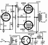
You should be getting 160VAC to give 226VDC for the valves. The first transformer steps down mains to 6VAC for the heaters. The second transformer is 9VAC so steps the 6VAC back up to 160VAC.
The output transformer is 12VAC not 6VAC as in your diagram. If the output valves are going rail to rail then I worked out you should be getting 15 watts peak or 10 watts RMS.
got any 6CW5/EL86? they would be a much better fit for the chosen output transformer and supply voltage. Too bad you're on the other side of the pond, I'd gladly send you a few. Maybe even try to grab some russian 6P43P-E, and try them in triode. They would likely work well too.
If you give 6V to a 9V winding, you will have 80V, not 120V.You should be getting 160VAC to give 226VDC for the valves. The first transformer steps down mains to 6VAC for the heaters. The second transformer is 9VAC so steps the 6VAC back up to 160VAC.
OK this is now a big topological departure from the spirit of Nigel's orginal design, but a man's gotta do what a man's gotta do.
It wasn't my design, it was just a simple circuit I found on the internet.
My part was to use back to back transformers for the power supply and use a power toroid for the output transformer.
You should be getting 160VAC to give 226VDC for the valves. The output transformer is 12VAC not 6VAC as in your diagram.
I can only report the way the amp came to me. The OT has definitely been wired for 6V, which makes some sense since a '6V transformer' is really a 7V winding that sags under load, which would be a turns ratio of 240/7 giving a nominal primary impedance of about 9.4k into 8 ohms. Not a million miles away from the customary 8k, and probably much closer given the low primary inductance.
Similarly, the 9V backward transformer is likely to have a no-load voltage of about 10V, meaning you only get 144Vac when driven with 6V, which amounts to 201Vdc -almost exactly what I measured off load. There's a big drop under load since you have the source impedance of two transformers!
Last edited:
There's a big drop under load since you have the source impedance of two transformers!
The first transformer is 50va so should be well within spec for the job of which 20VA is used for the heaters leaving 48VA to go to the second transformer.
The second transformer is 30VA so that should give 30 watts for the valves HT which is well above the 10 watts I original guesstimated.
Last edited:
I can only report the way the amp came to me. The OT has definitely been wired for 6V,
But its a 12 volt transformer ! Look on the label.
So I replaced the 9V backwards transformer with a 6V backwards transformer, giving me 220V HT. Now we're getting a more realiable 1W at close to 2% distortion @ 1kHz. At low frequencies it is actually worse, but it does looks better behaved -more like you expect for a transformer-coupled circuit.
I think the LM317 CCS is now the big handicap because it has barely any voltage headroom with only 6.5V across it. Also there is about 5mA mismatch between the EL84 cathode currents which could be affecting the output transformer, so let's do something about it...
Your power supply is different to how I thought I built it. There are two 6volt windings, one of which runs the heaters and the other goes into the 9VAC transformer. That way the heater winding didn't load the HVAC winding.
The way I received it the first power transformer has its two 6V secondaries wired in parallel, feeding both heaters and HV (keeping them separate wouldn't make much difference since they are magnetically coupled anyway). The OT is also a 0-6V, 0-6V transformer, with its secondaries wired in parallel.Your power supply is different to how I thought I built it.
There are two 6volt windings, one of which runs the heaters and the other goes into the 9VAC transformer. That way the heater winding didn't load the HVAC winding.

Last edited:
Nigel's design looks like a build around the Liebowitz simple self-inverting push-pull. I've had one of those on my to do list for a while but I'm going to drop the tone controls and use GNFB. The amp will be stereo with a single driver tube.OK this is now a big topological departure from the spirit of Nigel's orginal design, but a man's gotta do what a man's gotta do.
Last edited:
The way I received it the first power transformer has its two 6V secondaries wired in parallel, feeding both heaters and HV (keeping them separate wouldn't make much difference since they are magnetically coupled anyway). The OT is also a 0-6V, 0-6V transformer, with its secondaries wired in parallel.
I am maybe getting confused with a previous one I built.
I don't have a wiring diagram for the transformers just the pcb.
OK this is now a big topological departure from the spirit of Nigel's orginal design, but a man's gotta do what a man's gotta do.
Its not my design ! It was taken from a tube website. I just added power supply and output transformer.
I cant find a link to it. Have you got one ?
It's at that DIY projects site.
Attachments
My recent EL86 amplifier uses Antek Toroids for power and output, and the Toroid I have chosen for output is the AS-0505, with the secondaries in series for 10 volts, the impedance is 4232 ohms anode to anode, so it presents 2100~ ohms per pentode. Looking at the datasheet we see that this is a good load for output power and distortion, in comparison to the usual 1500R per tube that one often sees recommended for these tubes... Since many speakers have a dip in impedance at some points lower in the frequency response, a smidge higher impedance can help to keep the tubes happy. This isn't a junkbox part, its actually chosen to present an optimum load to the output stage. No "nonsense" here.
This same transformer would be a fantastic choice for parallel EL84 or 6V6 outputs as well.
What wattage would the AS-0505 be capable of? 10W? 20W? I am just about to put an order in for the AS-0506 which is 6V instead of 5V and would present a 5877 ohm load with 16 ohms on the secondary. This is for a guitar amp. I think that load would be fine for EL84's triode connected.
Since it's a 50VA coil, and your guitar's lowest note is 83Hz (isn't it?) that coil is good for the whole 50VA over the guitar frequency band AKA 50W. IMHO, you can easily get away with a smaller model if you like. The trade off is slightly reduced power because the smaller coil has a higher DCR.
- Home
- Amplifiers
- Tubes / Valves
- 10 watt valve amp project