Ok , i have 400v in Anode , in 300B.. and 63v 870ohms ( 73ma ) .. i think that is ok..
Buuuuuuuuuuuuuttttt , in d3a i have 158v anode with resistor 4,7K from 420v , and 6v 100ohm ( 60ma )... i dont know how..
Buuuuuuuuuuuuuttttt , in d3a i have 158v anode with resistor 4,7K from 420v , and 6v 100ohm ( 60ma )... i dont know how..
Attachments
-
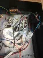 33862965_10156422405673686_9147356377050513408_n.jpg117 KB · Views: 373
 -
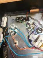 33921837_10156422405773686_4549689295086026752_n.jpg123.5 KB · Views: 319
 -
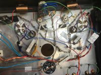 33987334_10156422405758686_3095394732797329408_n.jpg145.1 KB · Views: 306
 -
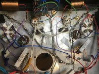 33990799_10156422405723686_3728940810259922944_n.jpg147.5 KB · Views: 315
 -
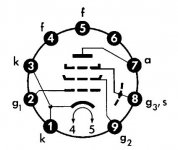 pinout.jpg24.9 KB · Views: 329
 -
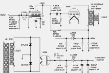 scha.jpg145.7 KB · Views: 217
In the diagram shows 100K for the stepped attenuator, put a 470K resistor from the 1K resistor connection to attenuator and ground.
D3A grid -- 1K -(put the 470K resistor here to ground)- attenuator.
It's important because between steps of the attenuator the grid of D3A could be floating.
D3A grid -- 1K -(put the 470K resistor here to ground)- attenuator.
It's important because between steps of the attenuator the grid of D3A could be floating.
Last edited:
Check all the connections of D3A. From pictures all looks good.
Maybe it is oscillating, put a pocket radio near and look for interference, much better with a scope.
Try to change the grid stoppers, the 1K resistors, try 10K par example, and put the body of resistor as close as possible to the grid connection on the socket.
Double check the resistors with your ohmmeter, 1% resistors are treacherous, it is easy to be confused by colors, and they are not the best for grid stoppers, carbon resistors are better.
Last edited:
I have 4v with 100ohms cathode in d3a..and 160v
It's impossible.
At -4V, 160V static operating point the trioded D3a anode (+G2) current practically zero.
Are you sure, that 100R resistor is 100R?
Is 100k (or any greater) FIX resistor is available from D3a grid to ground?
BTW (IMHO) your schematic's (in #1 post) some components value almost wrong.
As you can see D3a datasheet's 94. page https://frank.pocnet.net/sheets/128/d/D3a.pdf at -2V, 180V op. point anode (+G2) current about 15mA, not 22mA, as in your schematic.
Is use trioded D3a a VAS tubes for decades, mostly at 175-180V (depends of manufacturer and condition), 10mA anode, 2mA G2 currents, -2V bias (mostly I use old green LED instead of ugly R//C cathode complex).
The measurements don't make sense, is the meter OK?
The cathode resistor can't be 100 ohms, the measurements make no sense.
I have found quite a lot of variability in the D3A but these numbers are off the chart.
Oscillating? I have a 3.3K stopper resistor between the plate and screen grid. Cathode is grounded very directly in fixed grid bias applications or goes immediately to the bias Led. All leads as short as possible. I also often insert a 10 ohm resistor in series with the plate right at the socket.
- Status
- This old topic is closed. If you want to reopen this topic, contact a moderator using the "Report Post" button.
- Home
- Amplifiers
- Tubes / Valves
- D3A-300B Amplifier