I bought a couple pair of line transformers for PA constant voltage speaker lines. I rang out one of the first pair with the following results.
I injected about 5V (4.9V) into the 8 ohm secondary and got the following volatages...
Purple...117
Orange...82
Brown...57
Red...41
Blue...29
Yellow...20
Green...14
White...10
Black...0
If I did the math right that is about 4.5k end to end. There are several triads as you move down that are fairly symetrical...
With black as one end there are
Purple-Brown..4.5k
Orange-Red...2.25k
Brown-Blue...1.1k
Red-Yellow...560
Blue-Green... 280
Yellow-White...133
Out of the middle there is
Orange-Brown-Blue...935
This one is not quite as symetrical.
My question is whether there is any problem using primary windings skewed toward one end. I have some 32 ohm speakers that could make use of lowet ratio windings.
The first one sounds like the Parts Express 330-040. I have been using them in small guitar amps. I measured about 5K to 0-4-8 ohms (black - brown - purple). They will do 4 watts with a pair or 50C5's, 32ET5, or other radio output tubes on 165 volts of B+ (bridge rectified Triad N68-X isolation transformer).
I cranked the power supply up to 400 volts on a pair of 50C5's without blowing anything, and got over 25 watts at 1KHz in AB2, but the little OPT won't pass more than 10 watts at the low end of a guitar's range (about 80 Hz) without saturation. When you hit saturation the 50C5's glow like light bulbs. I doubt those transformers were ever intended or insulated for 300 - 400 volts of DC plus 10 watts of audio, so the reliability at this level could be iffy.
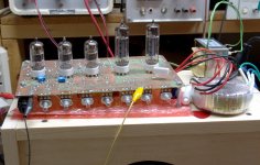
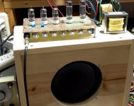
10 watts can be reached with 50C5's in AB1 on 330 volts (voltage doubler on the N68-X). The difference in volume level between 4 watts and 10 watts isn't real big, so I built a 4 watt amp and use it a lot. No issues in 3 years. It's plenty loud in my basement through a pair of 6 inch 91 dB Parts Express PA speakers.
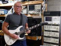
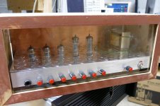
The little 4 tube amp chassis is sitting on top of the speaker cabinet to my right. The remains of its prototype is partially visible on top of the spectrum analyzer to the right of my head. The PE OPT is to the right of my ear with the unused wires sticking up into the air. I took this picture to show off the $50 Chinese guitar I bought new on Ebay. It plays and sounds so good that I sold my Squier Strat at the Dayton Hamfest last weekend.
I cranked the power supply up to 400 volts on a pair of 50C5's without blowing anything, and got over 25 watts at 1KHz in AB2, but the little OPT won't pass more than 10 watts at the low end of a guitar's range (about 80 Hz) without saturation. When you hit saturation the 50C5's glow like light bulbs. I doubt those transformers were ever intended or insulated for 300 - 400 volts of DC plus 10 watts of audio, so the reliability at this level could be iffy.
10 watts can be reached with 50C5's in AB1 on 330 volts (voltage doubler on the N68-X). The difference in volume level between 4 watts and 10 watts isn't real big, so I built a 4 watt amp and use it a lot. No issues in 3 years. It's plenty loud in my basement through a pair of 6 inch 91 dB Parts Express PA speakers.
The little 4 tube amp chassis is sitting on top of the speaker cabinet to my right. The remains of its prototype is partially visible on top of the spectrum analyzer to the right of my head. The PE OPT is to the right of my ear with the unused wires sticking up into the air. I took this picture to show off the $50 Chinese guitar I bought new on Ebay. It plays and sounds so good that I sold my Squier Strat at the Dayton Hamfest last weekend.
Attachments
The one I rang out today is 300-040.
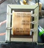
70V 10W Speaker Line Matching Transformer
The other pair I haven’t looked at yet are these.
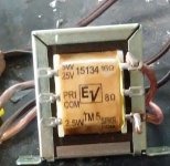
TM5 / TLM15134 5 Watt 25V / 70V 100V Speaker Line Matching Transformer
Any thoughts on whether there is any import to the layout of the taps as long as
I get the desired Z ratios?
I am considering triode strapped 12DT5
70V 10W Speaker Line Matching Transformer
The other pair I haven’t looked at yet are these.
TM5 / TLM15134 5 Watt 25V / 70V 100V Speaker Line Matching Transformer
Any thoughts on whether there is any import to the layout of the taps as long as
I get the desired Z ratios?
I am considering triode strapped 12DT5
Any thoughts on whether there is any import to the layout of the taps as long as I get the desired Z ratios?
Some of the tap combinations are not an exact balance, but then no OPT is perfectly balanced. The imbalance will usually lead to an increase in second harmonic distortion which is the norm in an SE amp, so the result is usually acoustically pleasing.
The concern is that the peak AC voltage swings at the unused ends of the windings could get pretty large if you are feeding a low impedance ratio in the middle. These things were never designed to eat a large DC and AC signal voltage at the same time, so the internal insulation may not be up to the task. I have seen one crank out 30+ watts with 400 volts of B+, but that was a test on one transformer. The next one could fry. Only testing will tell, but at $4 each, you don't have much to lose.
Using only part of the winding will reduce the already low primary inductance, so weak bass and possible excessive tube current if driven with heavy bass. I saw this when pounding a pair of 50C5's well beyond their comfort zone and I was using the entire primary. Again, testing is needed. The 12DT5 can pass some high current. I'm not sure which will win if the transformer is driven to saturation from a power supply capable of supplying high current.
I looked at this OPT as a super low budget experiment and so far all of my testing has been done with a $50 guitar amp in mind. The cheap tubes, cathode bias, and wimpy power transformer create a built in current limit function.
Tubelab_com, Wow! I think I see a Tektronix scope, an HP spectrum analyzer?.......
In my other (corporate) life I was an RF engineer at Motorola for 41 years, doing cell phone and two way radio design. I left that world 4 years ago, and have been slowly working on recreating the lab that I had there by bottom feeding on Ebay. Most of the equipment was purchased as defective or "parts units" on Ebay. Often the unit costs less than the shipping. I then repair or make good units out of multiple bad ones. Everything you see there is operational, and there are more goodies outside of that picture. It's safe to assume that ham radio and other RF projects will be coming as time and materials permit. The next hurdle is good SMD PCB prototyping.
I've got a pair of 70v line transformers that I picked up at a pro sound shop a few years ago, that are rated at 10 watts, and made by atlas sound. They are listed as 8k, with 0, 4, 8, and 16 ohm taps on the output. I believe the primary is set up with taps for 8k, 4k, 2k, 1k, 666, 400, 200, and COM.. With the 8k and COM taps as either end, and the 2k as the center tap, it works pretty well for triode connected EL84 or 6V6. The bass performance of these will be poor if expecting more than 4-5 watts from them. For guitar use they would be decent, however.
If looking at low price transformer options, I can highly recommend trying out power Toroids, especially if you don't need a super high ratio.
If looking at low price transformer options, I can highly recommend trying out power Toroids, especially if you don't need a super high ratio.
I can highly recommend trying out power Toroids, especially if you don't need a super high ratio.
Not all power toroids will work, and again it must be tested with the chosen tubes.
I have a screaming guitar amp that squeezes 18 watts from a pair of UL84's (45 volt 6CW5's) through an Antek AN-0509. Power went up to 20 watts when I used a real guitar amp OPT rated for 80 watts, so there isn't much lost in the Antek. The power transformer is a Triad FD8-120 isolation transformer.
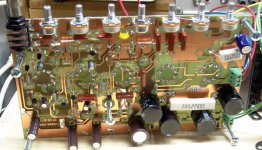
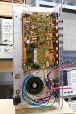
This was another amp designed for the Hundred Buck Amp challenge, and just squeezed in under $100. It's based on the "Marshall 18 watt" circuit and had far too much gain as built hence the hacks all over the circuit board. I plan to revisit this amp when time permits. Costs have gone up in the years since the challenge ended, but there are too many parts in this amp.....can it still be built for $100????????
Attachments

I love that PCB! A Marshall 18 clone is on my short list of builds to do for my father at some point, he's a pretty talented guitar player, and would love one for recording and playing on the worship team at church ")
The flea amplifier in my signature can be built just under $100 if one is to shop around, and I'm pretty confident it could be done around the same price if using certain cheap sweep tubes or Russian surplus. The small Toroids work fantastically well, even with a little 6SN7 as an output, and my current EL86 design also works great with Toroids, using the AS-0505 with series connected secondaries, went with higher supply voltage, so I went with 4k~ or so load for a smidge lower distortion.
The flea amplifier in my signature can be built just under $100 if one is to shop around, and I'm pretty confident it could be done around the same price if using certain cheap sweep tubes or Russian surplus. The small Toroids work fantastically well, even with a little 6SN7 as an output, and my current EL86 design also works great with Toroids, using the AS-0505 with series connected secondaries, went with higher supply voltage, so I went with 4k~ or so load for a smidge lower distortion.
Last edited:
Thanks George. I will check that out.
I just saw this thread on the cross coupled bias (which I had forgotten about.
Origin of the so-called "Blumlein Garter"
Might be a worthwhile thing to do with these small trannies.
I just saw this thread on the cross coupled bias (which I had forgotten about.
Origin of the so-called "Blumlein Garter"
Might be a worthwhile thing to do with these small trannies.
In case anyone is interested in the second transformer I linked above it rings out as follows. Note the markings on the tranny are confusing so I relabled them with letters. At the bottom I include a physical map of the two sides that matches the chart.
Input at 16 ohm tap.
Tap......N.....Z
A.......2.6......108
B.......3.8......230
C.......5.4......467
D.......7.6......925
E......10.8....1.85K
F.......15.2....3.7K
G......21.4....7.3K
PC=Primary Common
SC=Secondary Common
NC=No Connection
A-----16 OHM
PC---8 OHM
B------SC
G------E
NC---D
F------C
Input at 16 ohm tap.
Tap......N.....Z
A.......2.6......108
B.......3.8......230
C.......5.4......467
D.......7.6......925
E......10.8....1.85K
F.......15.2....3.7K
G......21.4....7.3K
PC=Primary Common
SC=Secondary Common
NC=No Connection
A-----16 OHM
PC---8 OHM
B------SC
G------E
NC---D
F------C
you can touch 40hz at 2w using the 1.25w inputs on 160v B+
at 6-8 w the low end falls off around 65hz
memory says 1.25w tap to plate 1, 5w to B+ and common to plate 2
1.25 = plate1
common ( highest resistance from 1.25w tap) = plate 2
roughly half resistance = B+
Resistance Won't be equal because turns on outside of coil are longer then inside coil
at 6-8 w the low end falls off around 65hz
memory says 1.25w tap to plate 1, 5w to B+ and common to plate 2
1.25 = plate1
common ( highest resistance from 1.25w tap) = plate 2
roughly half resistance = B+
Resistance Won't be equal because turns on outside of coil are longer then inside coil
Last edited:
I cranked the power supply up to 400 volts on a pair of 50C5's (
I'll bet they did. That's quite a bit over spec for 50C5s. What did you do with the screen voltage?
You can find better PP loadlines (data not provided in the spec sheet) if you exceed the stated plate voltage limit (135V).
Even a roughly symmetrical UL PP amp is possible with one (or possibly more) of these transformers: http://home.alphalink.com.au/~cambie/6AN8amp/M1115.htm
Best regards!
Best regards!
I am not sure what the primary inductance of these guys might be but it occurs to me that if one were to connect the ends of the primary together and use the center tap as the other connection it might work as a filter choke for low current (preamp) power supply or as a tail extender (for LTP).
- Status
- This old topic is closed. If you want to reopen this topic, contact a moderator using the "Report Post" button.
- Home
- Amplifiers
- Tubes / Valves
- rang out some OPTs. have a question