I'm laying out a stereo headphone 'spud' amp in a salvaged mono amp chassis that needs a 150VDC 120mA B+ supply. My design goals are:
1) Use the salvaged chassis' mounting holes with minimal modifications. I suck at metal work.
2) Use parts I have on hand. That's not much of a limitation, as I have too many parts in storage. I need to use 'em.
3) Use a vacuum tube based regulated or stabilized power supply. I just want some pretty tubes sticking up out of this chassis.
So...
My power transformer choices are an Allied N51X (115V:115V), an Allied N68X (115V:230V if wired backwards), or a salvaged 600VCT at about 150mA power transformer that also has 5V and 6.3V windings.
I have some vintage Radio Shack 12VCT 1.2A transformers if I need to make a separate heater supply.
I also have a couple of one-off chokes, 6H with DCR of 98 ohms and 10H with DCR of 141 ohms. I figure both of those are good for >110mA.
I was thinking of using an 0D3 VR tube, and I have a promising looking circuit simulated. However it will require a lot of high wattage power resistors to drop the volts necessary to feed the 0D3 its 20mA. I'm afraid the heat will be horrible. But having two pretty 0D3s sitting on the amp is an attractive idea.
Being that this chassis has three holes for octal sockets, I was thinking it could fit a tube series regulated B+ supply. I have some 6AS7G and I have way too many 12AX7s. I even have a few 6SL7 and 6AC7. The problem I'm running into is that I can't get anything I've designed to provide as low as +150V at the 110mA load I'll need, even though a 6AS7G with paralleled triodes should do this easily.
While I'm okay with taking a basic circuit and altering it to suit, it seems I am not competent to design a tube series regulator from scratch. I've tried; I've failed. So I'm asking for help.
Can anyone recommend a simple series regulator topology (using tubes, not a Maida) that can deliver +150V at 110mA?
Many thanks.
--
PS - I have a simple series regulator schematic using 6AS7G, 12AX7, and 0D3 that I was trying to modify to deliver 150V. I can post it this evening.
--
Last edited:
So...
My power transformer choices are an Allied N51X (115V:115V), an Allied N68X (115V:230V if wired backwards), or a salvaged 600VCT at about 150mA power transformer that also has 5V and 6.3V windings.
Are you going hollow state or solid state for the power supply? The Allied PTXs will work with a full wave doubler if solid state. For hollow state, the 600VCT is your only viable option.
I also have a couple of one-off chokes, 6H with DCR of 98 ohms and 10H with DCR of 141 ohms. I figure both of those are good for >110mA.
Go with the lower DCR here.
Being that this chassis has three holes for octal sockets, I was thinking it could fit a tube series regulated B+ supply. I have some 6AS7G and I have way too many 12AX7s. I even have a few 6SL7 and 6AC7. The problem I'm running into is that I can't get anything I've designed to provide as low as +150V at the 110mA load I'll need, even though a 6AS7G with paralleled triodes should do this easily.
Lots of possibilities for the series pass device. 6AS7s are good, and you can also try pseudotriodes as well. 6L6-oids work quite well for this.
Can anyone recommend a simple series regulator topology (using tubes, not a Maida) that can deliver +150V at 110mA?
Many thanks.
--
PS - I have a simple series regulator schematic using 6AS7G, 12AX7, and 0D3 that I was trying to modify to deliver 150V. I can post it this evening.
--
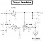
Yep. This was designed as a screen voltage active regulator. The 6AQ5 here is operating as a pseudotriode series pass element. It runs well below its PD rating for this application. Will need to be something else for this project. The reference voltage is from a 0A3 regulator (Octal type -- 75V) that doesn't need to draw much more than 7.0mA, as there is no current demand in parallel here. No need for hot, high wattage ballast resistors.
The error amp is an unbalanced LTP that makes good use of the otherwise hard to use 6X8 with its shared cathode. The pentode half is a high gain device which is what you want here, as it allows for enough NFB to stabilize the voltage and correct for ripple hum.
Attachments
I'd totally use that 6X8 based regulator. I think I can make a noval tube socket fit in one of the holes for octal sockets. I'd have to buy a 6X8 or two, as I don't have any.
Would it be possible to use a 6AC7 and a 6J5 (or similar) so I can use up metal octals I already have lying around?
I have nothing against UF4007 diodes and their like. The only reason I'd use a tube rectifier would be to get another glowing tube up on top of the chassis.
--
Would it be possible to use a 6AC7 and a 6J5 (or similar) so I can use up metal octals I already have lying around?
Are you going hollow state or solid state for the power supply? The Allied PTXs will work with a full wave doubler if solid state. For hollow state, the 600VCT is your only viable option.
I have nothing against UF4007 diodes and their like. The only reason I'd use a tube rectifier would be to get another glowing tube up on top of the chassis.
--
Last edited:
This is similar to what Miles posted, but uses 12AX7, 0C3, and 6AS7. You might get something out of the included write up as well:
La Luciernaga (Part 1, the PSU) – wauwatosa tube factory
This wouldn't do 150V output, but using a 0A3 voltage reference might get you close.
La Luciernaga (Part 1, the PSU) – wauwatosa tube factory
This wouldn't do 150V output, but using a 0A3 voltage reference might get you close.
A Maida could certainly be made with a tube pre drop device instead of a mosfet or bipolar power transistor. I've done it. It is a bit more complicated (for one thing mine used a separate screen supply), and would still use the 317, which may be distasteful if you're looking for an all-tube solution.
The 115 VAC secondary doesn't have enough voltage to give you room to regulate. If your only other choice is the 230 VAC secondary, a standard series-pass regulator could be made to work, but at 150V output, the solution will spill out the excess voltage drop across the pass devices as heat, which could become excessive. At 150 mA output, you will probably need two pass tubes paralleled together.
A solution I can see working would be to locate a transformer that had say 160 VAC secondary. I'd use silicon rectification, a pair of 6550's or 6L6's or whatever for pass devices, and a 12AX7 error amplifier. If you had a 100V voltage reference tube, could even throw that into the mix. Seems like that should work without too much trouble.
Morgan Jones' book Valve Amplifiers has a chapter devoted to power supplies, and the topology I described above is discussed in that chapter.
This is similar to what Miles posted, but uses 12AX7, 0C3, and 6AS7. You might get something out of the included write up as well:
La Luciernaga (Part 1, the PSU) – wauwatosa tube factory
This wouldn't do 150V output, but using a 0A3 voltage reference might get you close.
Thanks, I'm trying it out in LTspice. I can supply a .asc if that would be helpful. This circuit is attractive because I have all the tubes necessary in storage.
I substituted an 0A3 model (courtesy Stephie Bench). Fed by a raw B+ of +400V, and with a 110mA load, I get +171V DC at the output with the 50k pot cranked all the way.
Question:
Now that the 75V reference is in there, the 12AX7 triode on the left is running with its grid positive to its cathode by about 0.5V. The 12AX7 triode on the right is running with about -0.8 grid bias (still likely to draw grid current). Is this a problem in this type of usage?
Wait... Thanks to kward for bringing up 6L6GC or 6550 as a pass tube. These are good for 30W plate dissipation, and will drop a lot more volts than paralleled 6AS7 pair. Usually you don't want to drop that many volts, but here I do. I'm working on it...
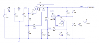
OK, here's what I got.
400VDC in, 160VDC out. Its efficiency is ghastly.
Uses a 6550A-triode for the pass tube, a 6SL7 for the error diff-amp, and a 0A3 for the voltage reference. Those were chosen because I have 'em.
LTspice says the ripple rejection is really good. It also says the 6SL7 sections are both biased with a negative voltage on their grids, which I figure is a good thing. The 6550A is dissipating 25 watts. The 0A3 is drawing almost 6mA.
How's it look?
--
Attachments
The 6550 looks like a much better pass tube choice here due to the very low VDC target output.
With the 6AS7, you must set the grid well below the cathode in order to drop enough voltage. The 6AS7 cathode is your output, so you're being asked to set the grid a good deal below the target output of 150V. The 0A3 sets the 12AX7 cathode to about 75V, so you have less than 150v-75v=75v to work with across the 12AX7. It just does not have the perveance to set the anode low enough. In fact, with a 400V input it doesn't look to me like you have any available voltage across the 12AX7 (just judging from plate curves here).
By contrast, the 6550 looks much better. To drop ~250V across it, the grid only needs to be 10-20V lower than the cathode. You still do not have much voltage room across a 6SL7 or 12AX7, but it's a much better situation than the 6AS7.
* A lower voltage reference would help, but I definitely understand the desire to add some glass for the fun/aesthetics of it.
* Although the gain of the error amp would be lower, you could also try simming other higher perveance dual triodes like 6DJ8, 5687, etc. That may give you more room to vary the output.
* A lower B+ than 400V will require you to drop less voltage across the pass device, both lowering dissipation and decreasing the negative bias required.
Cool parts bin project though!
I would go for a more simple solution.
Buy a cheap 24 or 25 volt 1 amp transformer and 'stack' the 115 volt transformer on top so you get 140 v ac or so. Then with silicon rectification you will have close to 200v HT which should be enough headroom for losses and proper regulation without the extra heat of another 150v at 110ma or so.
A VR150 /0D3 needs about 185v to work properly and 8 to 10 ma through it so it will need to go before the pass element. A 75 volt or 90 volt regulator might be better suited?
Here's a simple hybrid that I did recently with 0D3 and a MOSFET:

You'd still have sockets left over. Maybe use a tube rectifier or a couple damper diodes to use them up. Or build the above for each channel?
edit: IRF820 was what I used, I think. Ignore the transistor symbol.
You'd still have sockets left over. Maybe use a tube rectifier or a couple damper diodes to use them up. Or build the above for each channel?
edit: IRF820 was what I used, I think. Ignore the transistor symbol.
Also don't forget to bias up your pass tube filaments to the output voltage.
I think I would also consider biasing up the 6SL7 filaments. Since the pass tube filament circuit is biased at a different voltage than the 6SL7 filament circuit, it means needing separate filament secondaries. You might be able to "split the difference" so both heater-cathode voltage specs for both tube types are within tolerance, but I think that's a short cut measure. I would use separate filament circuits and bias each independently.
I think I would also consider biasing up the 6SL7 filaments. Since the pass tube filament circuit is biased at a different voltage than the 6SL7 filament circuit, it means needing separate filament secondaries. You might be able to "split the difference" so both heater-cathode voltage specs for both tube types are within tolerance, but I think that's a short cut measure. I would use separate filament circuits and bias each independently.
I'll make no bones about it: I like “sand-state” regulators for the simplicity of not having to deal with a significantly “raised cathode”. And the fact that unless they're thermally and/or electrically abused, they'll basically never “give up the ghost”.
Emitter follower (per Sodacose) or source followers (MOSFET, same service) do the job well. It is often a decent idea to have a back flow diode across the sand-state device so that if (like when "turning it off") there's more B+ on the output side than on the power transformer side, there is a way to safely bleed off the reversed potential.
Also, if you're willing to have a couple of sandy crystals working for you, then you can also implement either a slow-turn-on reference voltage, or a simple RC+transistor comparator delay of 15 seconds or so; makes for nice for the downwind vacuum tube amplifier.
Contrary to the advise of […] I prefer choosing higher henries than lower DC resistance when choosing random chokes for power supply purposes from my parts box. IF the power dissipation is within reason. Remember your friend: P = I²R, so with a DC resistance of 141 Ω, a pass current of 110 mA (your numbers), then
Not exactly an egg-fryer in dissipation! And the DC voltage drop is only 15.5 volts. Being “before the regulator”, the voltage drop is a GOOD thing. For Free.
Gotta run.
Goats to milk!
Cheese to make!
GoatGuy
Emitter follower (per Sodacose) or source followers (MOSFET, same service) do the job well. It is often a decent idea to have a back flow diode across the sand-state device so that if (like when "turning it off") there's more B+ on the output side than on the power transformer side, there is a way to safely bleed off the reversed potential.
Spend a nickel, save a buck.
Also, if you're willing to have a couple of sandy crystals working for you, then you can also implement either a slow-turn-on reference voltage, or a simple RC+transistor comparator delay of 15 seconds or so; makes for nice for the downwind vacuum tube amplifier.
Contrary to the advise of […] I prefer choosing higher henries than lower DC resistance when choosing random chokes for power supply purposes from my parts box. IF the power dissipation is within reason. Remember your friend: P = I²R, so with a DC resistance of 141 Ω, a pass current of 110 mA (your numbers), then
P = I²R
P = 0.11² A × 141 Ω
P → 1.7 W
E = IR
E = 0.11 A × 141 Ω
E → 15.5 volts
P = 0.11² A × 141 Ω
P → 1.7 W
E = IR
E = 0.11 A × 141 Ω
E → 15.5 volts
Not exactly an egg-fryer in dissipation! And the DC voltage drop is only 15.5 volts. Being “before the regulator”, the voltage drop is a GOOD thing. For Free.
Gotta run.
Goats to milk!
Cheese to make!
GoatGuy
150V was a standard voltage for military equipment so you'll find a few such regulators in the NAVAER handbook of preferred circuits Part 1
Handbook Preferred Circuits Navy Aeronautical Electronic Equipment : National Bureau of Standards : Free Download, Borrow, and Streaming : Internet Archive
Handbook Preferred Circuits Navy Aeronautical Electronic Equipment : National Bureau of Standards : Free Download, Borrow, and Streaming : Internet Archive
Here's a simple hybrid that I did recently with 0D3 and a MOSFET:
View attachment 683054
You'd still have sockets left over. Maybe use a tube rectifier or a couple damper diodes to use them up. Or build the above for each channel?
edit: IRF820 was what I used, I think. Ignore the transistor symbol.
Yes, I'd use two of these, one per channel. I have plenty of IRF820 and IRF840. I even have a few heatsinks. Two 0D3s glowing would be doubly fun. They also don't make heat, which is a plus. I'd still have room for a 5V4 rectifier or something like that, if I really needed to fill that last octal socket. But I don't, really.
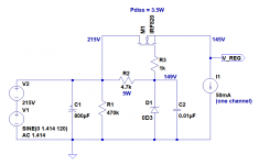
I also have a couple of vintage 500VCT 150mA transformers with 6.3V winding (but no 5V winding). I could use a choke input filter and get about +215VDC raw B+, then use this source follower-plus-0D3 after that, right? Okay, some questions about this:
- How much ripple rejection should I see from this circuit? If I set it up with +215VDC at the input with a 1.414VAC 120Hz sine wave riding on the DC. I see +145VDC at the output, but with only about -20dB of attenuation of that 120Hz sine wave. It does perform some voltage stabilization; it keeps the output voltage within +/-1VDC as the input voltage is varied +/-20VDC.
- This is with the IRF820 dissipating 3.5 watts, so a heatsink will be required. [Edit: It's labeled "Pdiss" on the schematic, but of course that should be Ddiss. Was thinking tubes again. Oops.]
Does this attached schematic look right?
--
150V was a standard voltage for military equipment so you'll find a few such regulators in the NAVAER handbook of preferred circuits Part 1
Handbook Preferred Circuits Navy Aeronautical Electronic Equipment : National Bureau of Standards : Free Download, Borrow, and Streaming : Internet Archive
Hey Merlin! That's very helpful indeed. Preferred Circuit No. 1 fills the bill. The only problem is the need for that negative supply. I guess I can figure something out. Thanks for this; I'll be looking into it.
Attachments
Last edited:
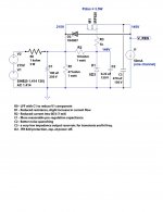
Looks correct! You might add protective zener to the source/gate or diode across the FET like GoatGuy mentioned, but what you have works.
The ripple rejection on this isn't as good as a feedback regulator like the series/pass ones earlier in the thread. Maybe a CCS feeding the VR is worth a sim?
The ripple rejection on this isn't as good as a feedback regulator like the series/pass ones earlier in the thread. Maybe a CCS feeding the VR is worth a sim?
Since these types of circuits work so well, I decided to work up a PCB with the option to run a stack of six Zener diodes as a voltage reference, and a pot/resistor in series across them for some voltage adjustment functionality. I've breadboard six so far, and wanted a nice board to be able to have them easily lashed up for future builds. I'm even working on a negative version. Assuming you used six 51 volt Zeners (like the 1N5262) you get just around ~300 volts out with an IRF820. Could easily run wire off board to a VR tube to use as a reference
")
It's still a rough draft, but if anyone has anything to suggest, go ahead and swing by my flea amp thread and let me know what you think. I'm wanting them to be a nice option for the DIY community.
(Note- I'm not actively selling anything at this time, simply throwing out the idea, and taking suggestions for anyone who has something constructive to add!)
Also, GoatGuy, check your PM inbox lol
Would the CCS replace R2 (4.7k 5W) in the schematic?
(Edit: If you meant just replace the whole thing with a series CCS and shunt 0D3, then no, that doesn't work nearly as well. Much higher levels of pwr supply ripple pass through.)
Right, I was referring to replacing R2 but maintaining the MOSFET pass device.
Lingwendil's board looks good too. I recently made some boards that use an LR8 in place of the zener string (yet to stuff and test though). Only problem is these don't glow
- Status
- This old topic is closed. If you want to reopen this topic, contact a moderator using the "Report Post" button.
- Home
- Amplifiers
- Tubes / Valves
- +150V DC Vacuum Tube Regulated Power Supply?