Zener diode and VR tube in series? How to bypass?
Okay, so I've been working on layout stuff. Making progress, but then I thought of something.
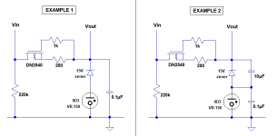
I want to raise the stabilized plate supply voltage to about 155V to 160V DC. In order to do that, I'd like to put a 15V zener diode in series with the 0D3.
First question is, can I do that?
Second question is, how best to install the bypass cap(s)?
- Do I have to have a single cap bypassing both the zener and the VR tube? Shown in EXAMPLE 1 in the accompanying schematic. Or...
- Can I bypass the zener with a larger value cap (say 10uF) and a separate smaller value cap (0.1uF) bypassing the VR tube? Shown in EXAMPLE 2 in the attached schematic.
I would think EXAMPLE 2 would be fine, but there always seems to be something I'm missing.
--
Okay, so I've been working on layout stuff. Making progress, but then I thought of something.
I want to raise the stabilized plate supply voltage to about 155V to 160V DC. In order to do that, I'd like to put a 15V zener diode in series with the 0D3.
First question is, can I do that?
Second question is, how best to install the bypass cap(s)?
- Do I have to have a single cap bypassing both the zener and the VR tube? Shown in EXAMPLE 1 in the accompanying schematic. Or...
- Can I bypass the zener with a larger value cap (say 10uF) and a separate smaller value cap (0.1uF) bypassing the VR tube? Shown in EXAMPLE 2 in the attached schematic.
I would think EXAMPLE 2 would be fine, but there always seems to be something I'm missing.
--
Attachments
Is it mandatory for one capacitor to bypass the entire string?
For a DC reference, keep the 0.1uF across the 0D3. Then from Vout use a series resistor and a
shunt capacitor to ground, forming an RC filter. This is more effective than a capacitor directly
across the Zener. Use a 400mW Zener instead, it will have better regulation at 7mA.
Last edited:
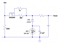
Like this?
(see attached)
That should work great. Or, use a VR90 and a VR75 in series instead of the zener/0D3
")
The RC filter is the way to go for sure. Makes a nice clean reference for a mosfet gate, and can be made to have a nice long time constant to give everyone time to play nice together.
That should work great. Or, use a VR90 and a VR75 in series instead of the zener/0D3
I have two things going on.
1) I don't have any VR90 tubes that would use octal sockets, and
2) I have a handful of 0D3 tubes I'm hell-bent on using.
I could get rid of the series zener entirely, but I would like that extra 15V of B+.
The RC filter is the way to go for sure. Makes a nice clean reference for a mosfet gate, and can be made to have a nice long time constant to give everyone time to play nice together.
But... If I get that long time constant using a large value series resistor where shown in the previous post's schematic, I'll get a lot of voltage drop, which defeats the purpose of adding the 15V zener in the first place.
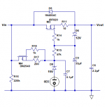
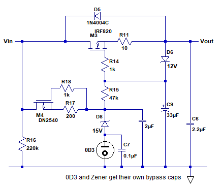
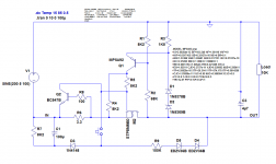
I think I'm confused about what you wrote (I hope so.) Here's the whole psu circuit (attached). I think R15 (47k) and C9 (33uF) create the long time constant you mentioned. Is what I have in this schematic adequate? Should the 0.1uF cap bypassing the zener and 0D3 be moved so that it bypasses the 0D3 only?
Sorry for my confusion...
--
Attachments
"Long" in this sense is relative, like a few seconds or so... 470k/10uF is what I usually use, giving an RC constant of 4.7 seconds or so, and in real operation it takes maybe fifteen seconds or so to go to more or less full output... and since you aren't drawing any real current the voltage drop is practically nonexistent, but I like the long constant for main PSU voltage on preamp/splitter stages or screens on big pentodes so that everyone has time to warm up before the party. Smaller works great too, personal preference really.
The schematic you've drawn up looks good. I would be inclined to go a decade smaller on the cap for 470k/3.3uF or whatever cap size you have handy, as shown your time constant is around 1.5 seconds or so, which in practice will be closer to six seconds total rise time, and will work well. Just my way of doing things (I like to use smaller caps wherever I can anywhere other than right at my PSU rectifier, just out of habit)
As far as bypass, I'm not so sure... I would be inclined to bypass both the Zener and the 0D3 to ground separately, but you might be fine simply throwing a cap across both. I would think doing some noise measurements both ways would be the best solution.
Hey, nothing wrong with using what you've got, I'm going to do a similar supply soon for one of the flea amplifier builds, it's been a while since I've used gas regs in a build, and I've got four 0D3s left begging for a use, among other assorted octal regs.
Thanks again for the guidance.
At turn-on, the peak DC voltage possible from the IRF820 gate to ground will be about +300V. The only 2.2uF or 3.3uF 400VDC caps I have on hand are fancy-schmancy polypro parts, which are physically too large. I bought a bag of 33uF 450V electrolytics for cheap from good ol' Apex Jr, which are nice and small, and have radial leads. So I was going to use those here. That's how I came up with the 47k/33uF RC combination.
- Perhaps I should increase the R to 120k?
- Any reason an electrolytic wouldn't work well here?
Like in the attached schematic?
At turn-on, the peak DC voltage possible from the IRF820 gate to ground will be about +300V. The only 2.2uF or 3.3uF 400VDC caps I have on hand are fancy-schmancy polypro parts, which are physically too large. I bought a bag of 33uF 450V electrolytics for cheap from good ol' Apex Jr, which are nice and small, and have radial leads. So I was going to use those here. That's how I came up with the 47k/33uF RC combination.
- Perhaps I should increase the R to 120k?
- Any reason an electrolytic wouldn't work well here?
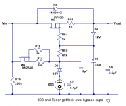
Lingwendil said:I would be inclined to bypass both the Zener and the 0D3 to ground separately
Like in the attached schematic?
Attachments
Last edited:


Some additional remarks: the examples I showed do not include protections: more complete circuits can be found here: Simple regulator for high voltage low current
My statement that these circuits are more effective is not just blunt and gratuitous: most of the efforts involved in this circuit are in fact wasted
The reason is that a simple, no-feedback source follower or capacitance multiplier has a finite ripple rejection, no matter how clean is the reference: the fault is on the lambda parameter, which has an equivalent in tubes (particularly triodes) or bjt's.
This means that M4, the regulator tube and C9 are mutually redundant.
The only way to overcome this limitation is to go closed-loop, as in my example, or to use a compensation scheme (I have published an example some times ago, for the Early effect).
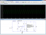
Why do the sim figures look so good for the IRF820-based follower? I suspect that their origin is to be found in the spice model, which does not include the lambda parameter, just a Rds value
My statement that these circuits are more effective is not just blunt and gratuitous: most of the efforts involved in this circuit are in fact wasted
The reason is that a simple, no-feedback source follower or capacitance multiplier has a finite ripple rejection, no matter how clean is the reference: the fault is on the lambda parameter, which has an equivalent in tubes (particularly triodes) or bjt's.
This means that M4, the regulator tube and C9 are mutually redundant.
The only way to overcome this limitation is to go closed-loop, as in my example, or to use a compensation scheme (I have published an example some times ago, for the Early effect).
Why do the sim figures look so good for the IRF820-based follower? I suspect that their origin is to be found in the spice model, which does not include the lambda parameter, just a Rds value
Wow, lots of great stuff to think about here! Thanks Elvee. Let me ask about one thing:
You're right! Since these are just models, meant to get me in the ballpark, do you think it would be helpful to use a different MOSFET model in place of the IRF820? I have one for STMicro STP8NM60 (600V) which has Lambda=0.005 in its model.
Do you think it might be helpful to add Lambda=0.005 to the IRF820 model, to see what happens?
More later. I haven't had time to look at your suggestions today. Weird day today, lots of distractions.
--
Why do the sim figures look so good for the IRF820-based follower? I suspect that their origin is to be found in the spice model, which does not include the lambda parameter, just a Rds value
You're right! Since these are just models, meant to get me in the ballpark, do you think it would be helpful to use a different MOSFET model in place of the IRF820? I have one for STMicro STP8NM60 (600V) which has Lambda=0.005 in its model.
Do you think it might be helpful to add Lambda=0.005 to the IRF820 model, to see what happens?
More later. I haven't had time to look at your suggestions today. Weird day today, lots of distractions.
--
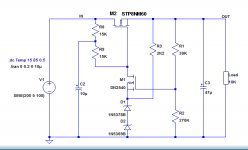
I put the version of the series regulator with 150V voltage reference, DN2540 error amp and STP8NM60 series pass element into LTspice. It does squash ripple a lot better than the cap-multiplier/source follower with VR.
Adding "lambda=0.005" to the IRF820 model only resulted in an error and failure to find DC operating conditions. That's a fail.
Differences in simulation between IRF820 and STP8NM60 are minimal.
If I did the vacuum tube version I'd have to make a single psu for both channels, so 115mA total load. I have three octal sockets in the chassis that could be used for power supply devices. I could see using a triode-wired 6AC7 and a paralleled-up 6AS7G along with the 0D3.
The solid state version would be easier to wire up.
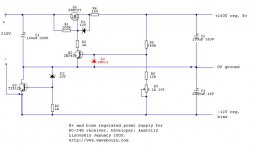
Here was my exercise with soft starting source of B+ and filament voltages from the single supply. It was an overkill, so I never used it any more.
Oops... sorry, I meant bias, not filament. Bias is shunt regulated, and acts as a reference voltage source for B+ regulator. They are connected in series. It starts slowly, while tubes do not draw current, and as soon as they start drawing current, voltages go up then get stabilized.
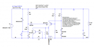
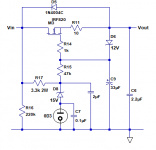
If the polarity of the ground is indifferent, it is possible to rationalize the circuit, and make it LDO, which can be useful in some situations.
A small complication is necessary to handle the startup, but it could be used to advantage to implement a standby switch with two (or maybe one) pushbuttons.
Otherwise, many options are workable, for example a RC circuit or a diode like here.
A small complication is necessary to handle the startup, but it could be used to advantage to implement a standby switch with two (or maybe one) pushbuttons.
Otherwise, many options are workable, for example a RC circuit or a diode like here.
Attachments
If the polarity of the ground is indifferent, it is possible to rationalize the circuit, and make it LDO, which can be useful in some situations.
A small complication is necessary to handle the startup, but it could be used to advantage to implement a standby switch with two (or maybe one) pushbuttons.
Otherwise, many options are workable, for example a RC circuit or a diode like here.
You can add a current sensing resistor in source with Zener to gate, to limit current. Also, a cap in series with resistor R6 and a button across it, for latching when output is shorted, and starting back manually.
Elvee said:most of the efforts involved in this circuit are in fact wasted
The reason is that a simple, no-feedback source follower or capacitance multiplier has a finite ripple rejection, no matter how clean is the reference: the fault is on the lambda parameter, which has an equivalent in tubes (particularly triodes) or bjt's.
This means that M4, the regulator tube and C9 are mutually redundant.
OK, I think that means the DN2540 CCS does not improve performance over a simple resistor to set current draw for the zener+0D3. If so, point taken.
Let's say I decide that the simpler form of this circuit has acceptable ripple suppression and output impedance for my needs. I would then use a 3.3k 2W resistor in place of M4 and R17, R18.
That would leave me with the IRF820 source follower (M3) with the 0D3 and 15V zener diode in series as a 165V reference, with the bypass caps for the zener and 0D3, and R16 (220k 2W, the bleeder resistor).
The 0D3 is just for looks. I have a few and I want to use them.
R15 (47k) and C9 (33uF) are meant to provide a slow ramp-up of voltage from the 0D3+zener. That sounds like it should be useful, it's very easy to implement, and I have those parts handy.
(See second attached schematic)
I can mount the zener diode, 220k and 3.3k resistors, and bypass caps for the zener and 0D3 right on the 0D3 octal socket. That leaves only the IRF820 and a handful of small resistors on the perfboard (which is now stuffed), with plenty of room for R15 and C9 (the slow-start RC network for the IRF820+zener+0D3).
--
I'm curious whether this simple source follower will do the job. If not, I can convert to the circuit you recommended earlier (see first attached schematic).
Attachments
I've used the simple no-feedback source follower to set B+ in circuits in the past, but it is preceded or followed by additional filtering. I haven't tried feeding the VR with a CCS personally and just suggested that on a hunch, thinking it may reduce ripple picked up at the gate of the pass MOSFET by increasing the impedance of the upper part of the reference divider.
What Elvee is saying makes sense to me though and I'm happy to learn something in this case. Saves parts cost/complication at any rate. I do like the simple all SS closed loop regulator Elvee posted, too. Like rongon, I like to add some visual interest to a PSU occasionally, hence the original FET+VR circuit.
What Elvee is saying makes sense to me though and I'm happy to learn something in this case. Saves parts cost/complication at any rate. I do like the simple all SS closed loop regulator Elvee posted, too. Like rongon, I like to add some visual interest to a PSU occasionally, hence the original FET+VR circuit.
- Status
- This old topic is closed. If you want to reopen this topic, contact a moderator using the "Report Post" button.
- Home
- Amplifiers
- Tubes / Valves
- +150V DC Vacuum Tube Regulated Power Supply?