I've got a bunch of odd value film caps from 4-9uF that I would be inclined to put there, or even have them locally at the circuit being fed.
Yes, exactly what I was thinking. I have some surplus store metallized mylar 4.7uF and 10uF that aren't too bulky. I'd install them from B+ at the OPT to 0V where the tube cathode load resistor and bypass cap will be grounded. One 'local bypass cap' for each channel.
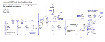
The design of the power supply for this idea would be:
- Choke input using 10H 141R and 330uF 400V electrolytic (because I have a couple),
- maybe something like 100R 5W and 330uF RC filter after the choke input filter,
- After that, each channel would get its own "Simple VR tube regulator" as in sodacose's schematic,
- Finally, each channel would get a 10uF film cap from B+ to 0V as close to the tube socket as possible.
That ought to be very good, no?
--

Sodacose said:I'd say you'll be good with the suggested filter.
LOL ... Yeah, okay, point taken.

See attached schematic. Does that look about right?
Wavebourn said:I'v e found augmented regulators are quieter than one with the same part count.
Sorry, what is an augmented regulator? I haven't heard that term used before. But I'm sure I don't know even 10% of what you know about it!
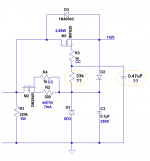
Lingwendil said:If you want a soft start feature you can add an RC filter in series with the gate resistor, with a largish resistor and a moderately sized film cap to ground you can play with parts values to get a nice ramp up feature that gives the VR tube time to settle.
That sounds like a great idea. But... questions:
RC filter = RC in parallel (tank circuit), or an R and a C in series?
Does the largish resistor go in series between the gate stopper resistor and the anode of the 0D3? And then the capacitor goes from jct of gate stopper and ramp-up R, to ground? Like in the schematic I've attached? (Which I doubt, but hey, I gave it a try...)
Attachments
Sorry, what is an augmented regulator? I haven't heard that term used before. But I'm sure I don't know even 10% of what you know about it!
2-step regulator, one powers another. Easy. If one, say, decreases ripples by 20 dB only, 2 of them would decrease by 40 dB. If each decreases by 40 dB, both would decrease by 80 dB.
Okay, I think that would be something like placing two 'soft' regulators in series, so that the end result is as good as or better than a single 'hard' regulator?
Something like how a 2-section CRC filter (say 33uF-1k-33uF-1k-33uF) attains much better filtration of power supply ripple than a single-section CRC filter of equal values (50uF-2k-50uF). Yes?
Something like how a 2-section CRC filter (say 33uF-1k-33uF-1k-33uF) attains much better filtration of power supply ripple than a single-section CRC filter of equal values (50uF-2k-50uF). Yes?
Like in the schematic I've attached? (Which I doubt, but hey, I gave it a try...)
Like shown in your second schematic here. I'll redraw it my way if needed

100k/1uF would be a decent start, or even higher, I've gone 100k/10uF before.
Last edited:
Okay, I think that would be something like placing two 'soft' regulators in series, so that the end result is as good as or better than a single 'hard' regulator?
Something like how a 2-section CRC filter (say 33uF-1k-33uF-1k-33uF) attains much better filtration of power supply ripple than a single-section CRC filter of equal values (50uF-2k-50uF). Yes?

Sodacose said:XSE10-50-8k? First time I've seen that OPT. Nice that old blue is starting to do some headphone type outputs.
It's their only one like that, afaik.
Like shown in your second schematic here. I'll redraw it my way if needed
If that's correct, then great!
100k/1uF would be a decent start, or even higher, I've gone 100k/10uF before.
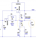
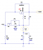
If I place a series R of 2.2k 'on top' of the 0D3, the output from the source follower increases to +156V, up from +142V (see attached diagram; note that it shows 1.5k for that R). This allows a bit more headroom from the amplifier, for when I use 300-ohm cans.
At the same time, if I were to install a 6AX4 or 6AU4 damper diode in series with the B+ before the choke, wouldn't that provide a slow enough B+ ramp-up for the 0D3 to stabilize? I have a 6.3V 2A winding available on the power transformer and an octal socket, both of which aren't being used at this point.
Another possible benefit from using a series damper diode is that it would allow me to use a single LC choke input filter with +189V out to the drain of the source follower IRF820 (and no RC stage after the LC). I could then use one regulator for both channels, and still keep the power dissipated by the source follower at an easy-to-deal-with 4W.
What do you think?
--
Attachments
Last edited:
XSE10-50-8k? First time I've seen that OPT. Nice that old blue is starting to do some headphone type outputs.
Can't find them on Edcor website. Asked Brian, but he did not answer yet.
Can't find them on Edcor website. Asked Brian, but he did not answer yet.
I believe he means this guy, with a 50 ohm secondary selected-
EDCOR - XSE10-8K
Thanks. I need both 8 and 50 Ohm. Also, their small transformers have too low inductance, compared to GXSE.
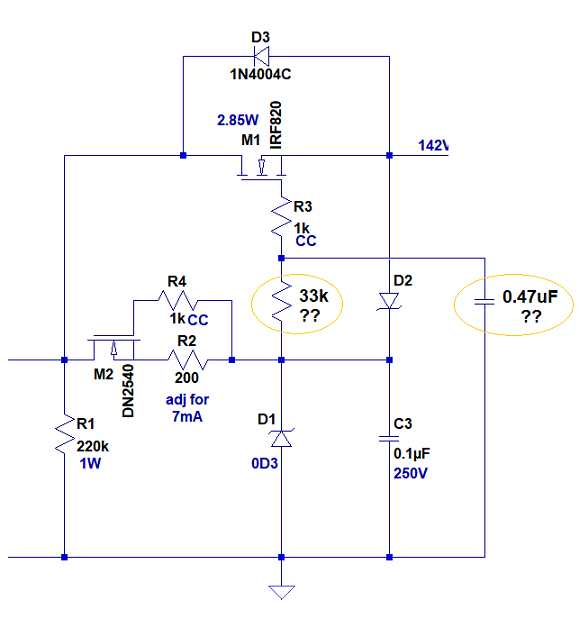
No comments on the series resistor sitting on top of the 0D3 to raise the B+ feed by a few volts? As in this:
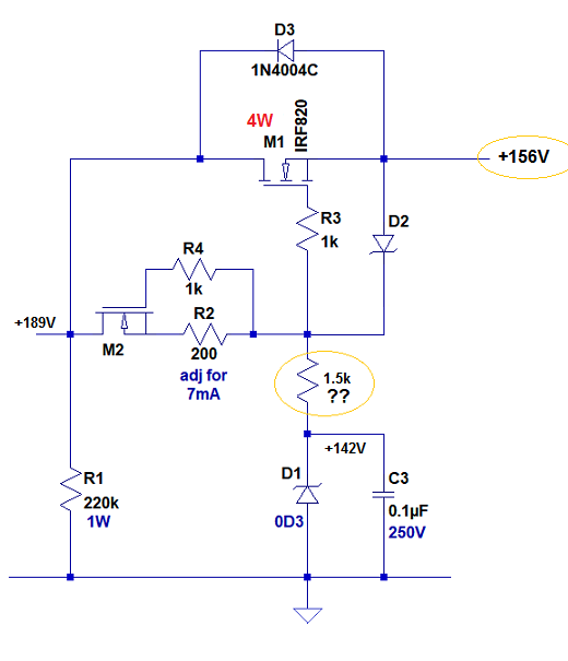
1.5k is the value LTspice says would raise the B+ from +146V (a little too low) to +156V (just right).
Also, no comments about using a series 6AX4 damper diode to give soft-start to the B+? Would that make the series RC ramp-up filter unnecessary?
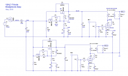
I've attached a schematic and .asc of the proposed stereo headphone amp circuit.
--
1.5k is the value LTspice says would raise the B+ from +146V (a little too low) to +156V (just right).
Also, no comments about using a series 6AX4 damper diode to give soft-start to the B+? Would that make the series RC ramp-up filter unnecessary?
I've attached a schematic and .asc of the proposed stereo headphone amp circuit.
--
Attachments
Last edited:
I would rather a pair of Zeners than the resistor, but with a CCS feeding either way is likely to be just fine.
As for the damper diode, I personally would prefer the RC filter, as it's one less filament to worry about. 1M/1uF or 100k/10uF would give you a couple second rise time, which should be plenty sufficient. You don't really, need it, but it's a nice feature to have.
As for the damper diode, I personally would prefer the RC filter, as it's one less filament to worry about. 1M/1uF or 100k/10uF would give you a couple second rise time, which should be plenty sufficient. You don't really, need it, but it's a nice feature to have.
I would rather a pair of Zeners than the resistor, but with a CCS feeding either way is likely to be just fine.
Of course! Zeners! I'm such a dummy. Of course a couple of 5.6V zeners would be the answer. I have dozens of them. Used this way, they'd be dissipating very little power (5.6V at 8mA = 45mW).
As for the damper diode, I personally would prefer the RC filter, as it's one less filament to worry about. 1M/1uF or 100k/10uF would give you a couple second rise time, which should be plenty sufficient. You don't really, need it, but it's a nice feature to have.
I see your point, definitely. Thanks for sharing that trick; it's a good one. But I'd like to fill up the three pre-punched holes in the top of this ugly chassis with octal tubes of some kind. Two 0D3 and a 6AX4 would look nice up there, and I have the heater winding ready and waiting.
Or why not do all of it? Put in the couple of zeners to raise the B+ and the RC filter to ramp up the voltage slowly to the 0D3 and the 6AX4 in series before the input choke...
I need to spend a couple hours pondering the layout. I always screw up that part of the process. I need to wire up some perfboards with the MOSFETs and supporting passive parts, see how much room that will take up. Once that's done I'll be able to see what needs to go where. Hopefully I'll have a few hours I can devote to this over the weekend.
--
Last edited:
I should post a photo of the chassis. Oh wait... Here's one just like it:
It's got a lot of holes. I cleaned mine up and painted it bronze hammertone.
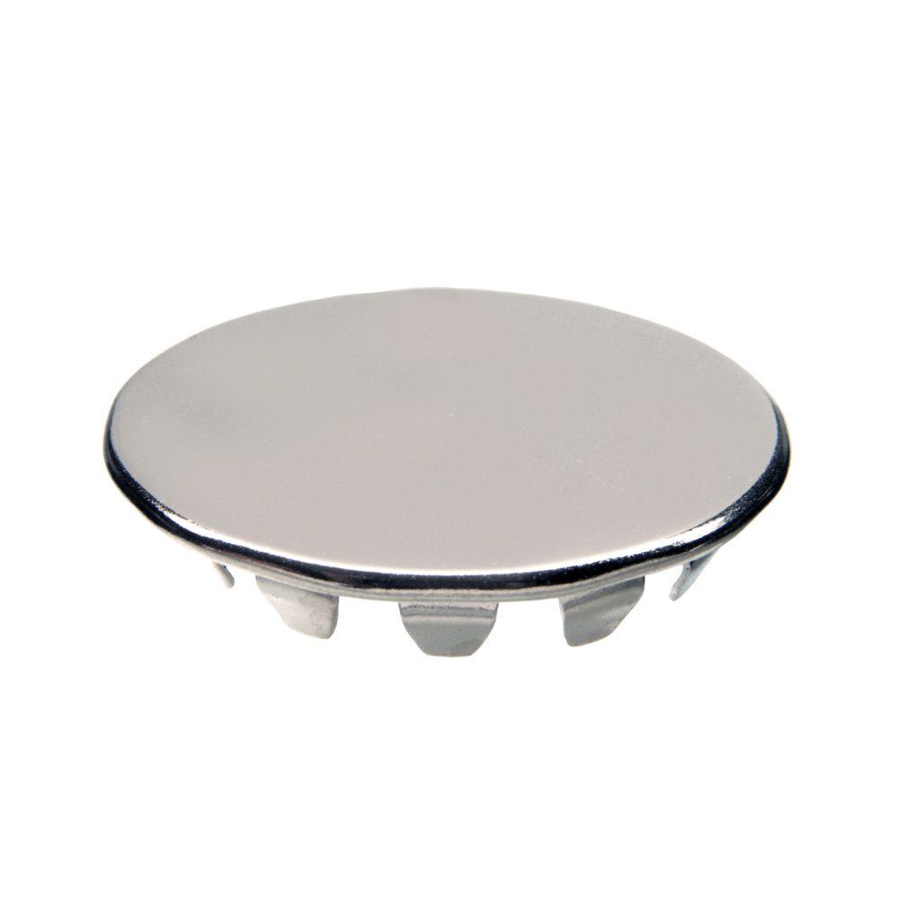
If the holes for the octal sockets are 1-1/4" diameter, I could put a couple of these where needed:
Or something...
--
An externally hosted image should be here but it was not working when we last tested it.
It's got a lot of holes. I cleaned mine up and painted it bronze hammertone.
If the holes for the octal sockets are 1-1/4" diameter, I could put a couple of these where needed:
Or something...
--
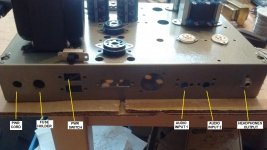
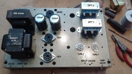
I got a moment to ponder layout issues. Here's what I have so far (see attached photos).
- The two Edcor OPTs will go underneath, in the positions shown.
- A RatShack 12VCT 1.2A transformer will also go somewhere underneath the pwr transformer and choke.
- I'm thinking of AC heating the 12HL7s. If that doesn't work out, I'll do the FWB rectification > LM317 thing.
- I think I can squeeze a vol ctrl pot in between the input jacks and the headphone out jack, on the front panel. Or I guess I could have it sticking up, in front of the two 12HL7s.
I'm open to any suggestions.
Attachments
Last edited:
- Status
- This old topic is closed. If you want to reopen this topic, contact a moderator using the "Report Post" button.
- Home
- Amplifiers
- Tubes / Valves
- +150V DC Vacuum Tube Regulated Power Supply?