The ripple rejection will be 3x worse. Is it a problem, that's for you to decide.1) I got confused between my original circuit and your modification for more feedback/lower gain, and I wired in 4.7k ohm resistors for R4 and R5 (they're 15k in the previous schematic) but left in R3 (the current setting resistor for the VR tube). In simulation the only difference I see is about 1.5mA more current drawn by M1 and the VR tube, but no change in performance. Do you see a problem there?
The pole has an effect on ripple up to very large time-constants: approx. 2s, then other effects kick in, and there is no more improvement to be gained.2) Assuming R4 and R5 being 4.7k ohms is OK, what pole is acceptable for the low pass filter formed by R4 and C3? That looks like a decoupling network for M1, with R5 as the drain load resistor. Am I close?
Here again, that's for you to decide: if you want the absolute maximum ripple rejection, you need 220µF to 470µF for C3 with 4K7, but that is really massive
See above: there is a strict proportionality between the cap size and the rejectionIf that is the case, then we'd want R4/C3 to attenuate frequencies down as low as possible. If I'm using 4.7k for R4, do I want to use at least 22uF or 33uF for C3? Or would 10uF still be OK there?
10µF is Ok, an E-cap is preferable as it will introduce a bit of damping3) What value of capacitor is appropriate for C4 (shunting the regulator's output)? Would 10uF be fine there? Or do we want more, like 47uF?
Would making C4 a film capacitor be beneficial? If so, what value cap is too small?
It would be prudent to keep the gate to source zeners4) As you can see, I removed R16, and I've left out the diodes D5, D9 and D10 from the previous schematic.
--
Thanks Elvee.
It will be difficult to remove those 4.7k resistors without tearing everything up. But I have a couple of 200uF 330V caps that are physically small enough to use for C3, so it looks like it'll work out.
I'll put the gate-source zeners back. Any difference between using 8.2V, 10V, 12V, or 15V zeners? My limited understanding is that you want to choose a value that won't let the gate-source voltage go wildly high. The operating gate-source voltage is usually about +4.5V. I was planning to use 12V 1W zeners, but I'm wondering why 8.2V wouldn't be safer.
I was thinking, since I have an LCRC raw supply that already reduces ripple to acceptable levels, adding the regulator is more about achieving super-low power supply impedance than ripple rejection.
In simulation, I've put a 2V RMS 120Hz sine wave in series with the basic DC voltage, to simulate ripple (I know there are better ways to do this, but this is all I know how to do).
I have an LC (choke input) filter using 10H (141 ohms) and 100uF. After that stage, the 2V RMS ripple has been knocked down to only 10mV. I've even applied a 10V RMS 120Hz sine wave in series with the DC voltage, and ripple is beaten down to only 30mV. Pretty effective, I'd say.
After that comes an RC filter of 220R and a whopping 800uF. After that, the ripple is down in the microvolt range.
And after that comes the regulator!
So, question #1:
Does it really matter what value I choose for C3 (the decoupling cap after the R4 4.7k)? Whether I put 10uF or I put 200uF, I see no ripple on the output (in simulation). I also see no difference in how much audio signal is reflected back on the regulated B+. It always shows about 0.4mV peak with about a 1.6V peak 1kHz sine wave applied to the 12HL7 grid. I don't know how to calculate the power supply impedance from that, but that baby's STIFF.
Question #2:
More of a construction question. Does it matter where I place the gate-source protection zeners? A schematic will make it easier to explain the question.
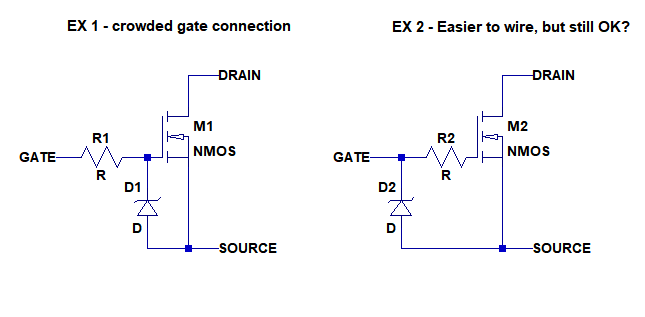
In EX 1, the zener cathode and gate stopper resistor are directly connected to the MOSFET gate. I'd think this is the ideal way to connect these. However, it makes an awful clump right at the MOSFET gate. It would be much easier to connect these devices as shown in...
EX 2, where the gate stopper resistor is connected directly to the MOSFET gate, but the zener's cathode is connected to the *other* side of the gate stopper (R2). This puts R2 in series between the zener's cathode and the MOSFET gate. Is that a problem?
Thanks again.
--
PS - I posted Question #2 about an hour ago in the Solid State forum, but no replies yet.
In simulation, I've put a 2V RMS 120Hz sine wave in series with the basic DC voltage, to simulate ripple (I know there are better ways to do this, but this is all I know how to do).
I have an LC (choke input) filter using 10H (141 ohms) and 100uF. After that stage, the 2V RMS ripple has been knocked down to only 10mV. I've even applied a 10V RMS 120Hz sine wave in series with the DC voltage, and ripple is beaten down to only 30mV. Pretty effective, I'd say.
After that comes an RC filter of 220R and a whopping 800uF. After that, the ripple is down in the microvolt range.
And after that comes the regulator!
So, question #1:
Does it really matter what value I choose for C3 (the decoupling cap after the R4 4.7k)? Whether I put 10uF or I put 200uF, I see no ripple on the output (in simulation). I also see no difference in how much audio signal is reflected back on the regulated B+. It always shows about 0.4mV peak with about a 1.6V peak 1kHz sine wave applied to the 12HL7 grid. I don't know how to calculate the power supply impedance from that, but that baby's STIFF.
Question #2:
More of a construction question. Does it matter where I place the gate-source protection zeners? A schematic will make it easier to explain the question.
In EX 1, the zener cathode and gate stopper resistor are directly connected to the MOSFET gate. I'd think this is the ideal way to connect these. However, it makes an awful clump right at the MOSFET gate. It would be much easier to connect these devices as shown in...
EX 2, where the gate stopper resistor is connected directly to the MOSFET gate, but the zener's cathode is connected to the *other* side of the gate stopper (R2). This puts R2 in series between the zener's cathode and the MOSFET gate. Is that a problem?
Thanks again.
--
PS - I posted Question #2 about an hour ago in the Solid State forum, but no replies yet.
I can't add too much to question #1, other than I would be inclined to use a smaller amount of capacitance if it will work.
For question #2, I've always run zeners directly to the gate, as closely to the body of the FET as is practical, to limit any stray capacitance, and run a separate grid stopper straight to the pin as closely as possible to the body of the FET as well. I would recommend example #1.
For question #2, I've always run zeners directly to the gate, as closely to the body of the FET as is practical, to limit any stray capacitance, and run a separate grid stopper straight to the pin as closely as possible to the body of the FET as well. I would recommend example #1.
Hey BTW, I did a little simulation comparison between a passive supply and Elvee's series/NFB regulator.
The passive supply consists of a choke input filter followed by an RC filter, in common to both channels. Then each channel's 12HL7 gets an RC filter of its own, to bring the plate supply down to the target +160V.
10H/390uF -- 220R/390uF (common to both channels) -- 470R/47uF (for each channel)
I got those values from PSUD2 simulations. I measured the offline voltages and the DCR of the primary and secondaries of the power transformer I'll be using and fed that data into PSUD2.
The series/NFB regulator is as in the previous post.
Both methods make ripple effectively disappear. The passive supply reduces ripple to 0.288mV according to PSUD2.
The difference?
In LTspice, you can plainly see that there's an infinitesimally tiny bit of audio signal riding the B+ when fed from the series/NFB regulator. When the 12HL7 grid is fed 1.6V peak (for 4V peak out into a 300R load), there's only 0.2mV peak audio signal appearing on the B+ rail.
For the passive supply, under the same conditions, there's 25X that, or 5mV peak audio signal riding on the B+.
I have the regulators almost wired up on perfboard.
I think I'll wire up the amp with the passive 470R/47uF feeding each channel's B+, until I get it running. That way I can listen to it with the passive supply and make sure I'm not getting hum from heaters or anything like that. Then once I'm sure everything's working well enough, I'll remove the final RC filters and replace them with the regulator board. It will be interesting to hear the difference.
Onward!
--
If the upstream filtering is already very good, you could dispense completely with C3, but even if the sim's resolution is too coarse to show it, C3 will have an effect, up to ~470µF. Will it translate into an audible hum? That's a different question, and there is no simple and direct answer.So, question #1:
Does it really matter what value I choose for C3 (the decoupling cap after the R4 4.7k)? Whether I put 10uF or I put 200uF, I see no ripple on the output (in simulation). I also see no difference in how much audio signal is reflected back on the regulated B+. It always shows about 0.4mV peak with about a 1.6V peak 1kHz sine wave applied to the 12HL7 grid. I don't know how to calculate the power supply impedance from that, but that baby's STIFF.
The output impedance will not be greatly influenced by C3, it will stay at around 80 milliohm IIRC, and any influence will work in the opposite direction: if you eliminate C3 completely, the regulator's loop gain will be increased, thus reducing the output impedance (it is just a factual description, it does not necessarily mean that it is desirable to do so)
I would go with #2 here. R2 serves as a stopper that loads down parasitic resonant circuits/neutralizes negative resistances reflected by Miller Effect from dirty admittances in the drain circuit. The Zener simply prevents over voltages on the gate insulation, and will work if connected to the far side of the gate stopper.Question #2:
More of a construction question. Does it matter where I place the gate-source protection zeners? <snip>
+1. This is preferred because it incorporates the zener capacitance directly into the pre-existing gate-source capacitance, rather than creating an unnecessary extra pole as in #2.I would recommend example #1.
Thank you one and all for your replies. I always learn a lot from you all.
It seems the consensus is that the zeners go directly from gate to source. Fair enough.
Good point (TheGimp) on C4. Elvee mentioned that 10uF was plenty, and that an electrolytic cap is better than a low-ESR film cap in that spot for damping (I assume provided by the higher ESR of an electrolytic type).
Right now I'm working on layout issues and heater wiring, in the hour or so I can devote to the project in the evenings after work. Limited time and my own tendency to overthink everything keeps things moving slowly...
- Status
- This old topic is closed. If you want to reopen this topic, contact a moderator using the "Report Post" button.
- Home
- Amplifiers
- Tubes / Valves
- +150V DC Vacuum Tube Regulated Power Supply?