The following image depicts a damping factor control from an Electro-Voice A30, which was adjustable from 0.1 to 15. Given that a) such a ganged pot would be a custom item, and b) it's unlikely anyone would want the low end of the range today, at what position would this pot yield the highest damping factor? (The wiper of the top pot is connected to the output transformer 16 ohm tap, the junction between the pots is speaker common)
Attachments
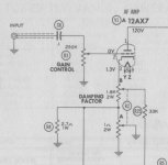
The 16 ohms is the NFB tap. The other is the Positive feedback tap. To increase damping factor (reduce output impedance) you want to increase NFB and remove PFB. You can do that by moving the NFB (upper) wiper away from ground and the grounded PFB wiper (lower) toward FB tap.
Hi Dave,
For normal speakers, the higher DF is the better way to go. Given that the high end of this amplifier is only 15 ... Most SS amplifiers are 40 or better. Tube amps can range all over the place, but many sit around 8 ~ 10. Single ended types without feedback are probably a fraction.
-Chris
For normal speakers, the higher DF is the better way to go. Given that the high end of this amplifier is only 15 ... Most SS amplifiers are 40 or better. Tube amps can range all over the place, but many sit around 8 ~ 10. Single ended types without feedback are probably a fraction.
-Chris
Hi Dave,
The speakers I made like higher DF. But there is a big difference between a DF of 20 and 80. Not nearly difference from 100 to 1000 as you lose the higher DF to connection resistance and sometimes wire impedance. But 20 is a very low damping factor compared to what I normally experience.
-Chris
The speakers I made like higher DF. But there is a big difference between a DF of 20 and 80. Not nearly difference from 100 to 1000 as you lose the higher DF to connection resistance and sometimes wire impedance. But 20 is a very low damping factor compared to what I normally experience.
-Chris
I can’t be bothered… you do the math. Here is a hint: Speaker Wire and Effective Damping Factor
Dave
Dave
Hi Dave,
Thanks. I thought from your comment that you had worked it out.
A simpler way to look at it. Including the crossover will drop the effective damping factor at the terminals of the driver to 0.5 at the crossover frequency where the crossover is 3dB down. That's because the crossover series impedance = the woofer impedance at the crossover point. How's that for ugly? This was a 2 way example of course.
-Chris
I am afraid that I respectfully need to disagree with Allensoncannon (post #2).
Let us look at the positive feedback only for the moment, i.e. leave NFB as constant at whatever value. To analyse in a descriptive way: Infinite damping factor results when the amplifier output impedance as seen by the loudspeaker (driver) is zero. (This per the common definition of D.F. which is misleading to start with, but let us not go there - one thing at a time!).
A physical way to view this is that whatever signal voltage drop occurs at the amp output as a result of the load of a loudspeaker, said drop is countered exactly by some means, then the resultant output siganal will remeain constant regardless of what load is applied, down to even no load impedance.
This characteristic can be achieved by positively feeding back just enough signal (in a sense increase amplifier gain) to counter/cancel said 'output' voltage drop. Such feedback needs to be load-sensitive; that is the sensing of exactly what load is applied. For this feature not to cause oscillation at some point, it is best included inside an existing NFB loop - which is the way it is used in amplifiers includine this feature.
[Interjecting: It would be clear that such positive feedback can in fact also over-compensate as it were. In that case, with the application of positive feedback,the output would go slightly larger than the no-load figure. In this way one can also 'compensate' for loudspeaker cable resistance. And it is done in practice - but let us stick to the present simple case.]
As the lower pot (in the sketch) slider is at the higher side, the positive feedback is nullified, thus as per classic topology: NFB can be increased but only to a point (before instability creeps in).
This should make it clear that within a NFB loop, 'virtual' amplifier output impedance and thus DF can be managed by the lower pot. Why this is coupled to an adjustment of NFB is at present not clear to me - as said the two things were usually considered separately in past designs. (To my knowledge the "Connoisseur tube amplifier" of about 1956 was the first example I saw with this feature.)
Combining the two as in the provided schematic, would see a decrease in amplifier gain controlled by the top control. (The change of positive feedback inside the loop will not be noticed, as the outside NFB loop will compensate for whatever gain difference occurs inside it.
This the basic explanation. Design would involve the roles of phase changing elements inside the outside loop and a few more matters regarding driver charaterisics. Thus, a certain feedback design is really best done with the driver(s) fully includud in the mix. Just as described in its simplest way, it can still cause some improvement in sound output.
If the circuit can be interpreted in any other way, I would like to hear about it, or perhaps read about it somewhere?
Interesting and make sense. Thanks. That said, I also happen to have an Electro Voice A30 in my to-work-on bin. It has a bad power transformer and I haven't find a replacement nor figure out how to fit two in that small box yet. I did measure the DF pots. At it's lowest DF setting, the upper pot is at its highest R, 1.8K (min NFB), the lower is also it's highest R (~0.7R, max PFB). I don't think the EV A30 is using resonant to increase its DF. It appears to me, the designer only want to use PFB to reduce output impedance and decrease DF. Also the max DF number on that unit only go up to 10.
The 16 ohms is the NFB tap. The other is the Positive feedback tap. To increase damping factor (reduce output impedance) you want to increase NFB and remove PFB. You can do that by moving the NFB (upper) wiper away from ground and the grounded PFB wiper (lower) toward FB tap.
No, increase of NFB by voltage and PFB by current both increase damping factor. Increase PFB by current too much, and you can get a negative output impedance that can cause the speaker to oscillate.
Last edited:
Too much positive feedback causes the amplifier to oscillate. When adequately applied, an interesting lowering of the electrical damping value (Qes) of the driver occurs.
The scheme is explained in one the first papers on bass-reflex by Thiele published in the JAES. It is the base of Stahl's subwoofer, one of the first commercialised, and also of many Yamaha products since thirty years.
The scheme is explained in one the first papers on bass-reflex by Thiele published in the JAES. It is the base of Stahl's subwoofer, one of the first commercialised, and also of many Yamaha products since thirty years.
Last edited:
From Dan J. Tomcik and Alpha M. Wiggins, "New Amplifier has Bridge Circuit Output" published in the November 1954 issue of Audio magazine.
"This variable internal resistance allows the amplifier to be adjusted so that it presents the optimum damping factor for critically damping any speaker combination. Damping factors greater than unity are achieved by varying amounts of negative voltage feedback from the output to the first stage cathode circuit as shown in Fig. 3. Conversely, damping factors less than unity are produced by varying amounts of negative current feedback obtained from the low resistance inserted in the speaker circuit. By combining the two types of feedback with the aid of a ganged potentiometer as shown, the overall feedback is maintained constant. The damping factor, however, is varied over a wide range. Needless to say, the maximum power available from the amplifier is independent of the damping factor and remains constant."
"This variable internal resistance allows the amplifier to be adjusted so that it presents the optimum damping factor for critically damping any speaker combination. Damping factors greater than unity are achieved by varying amounts of negative voltage feedback from the output to the first stage cathode circuit as shown in Fig. 3. Conversely, damping factors less than unity are produced by varying amounts of negative current feedback obtained from the low resistance inserted in the speaker circuit. By combining the two types of feedback with the aid of a ganged potentiometer as shown, the overall feedback is maintained constant. The damping factor, however, is varied over a wide range. Needless to say, the maximum power available from the amplifier is independent of the damping factor and remains constant."
- Status
- This old topic is closed. If you want to reopen this topic, contact a moderator using the "Report Post" button.
- Home
- Amplifiers
- Tubes / Valves
- E-V A30 Damping Factor Adjustment