Dear Sirs.
I am hoping to reconfigure this circuit as to omit the first stage and still maintain the properties of FB circuit.
By this i am hoping to reduce gain of the amp.
May i be so free as to ask of you, please advice?
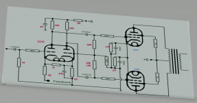
Pic#1
1st stage and FB and actual values:

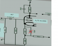
Pic#2
Actual values as edited:

I am hoping to reconfigure this circuit as to omit the first stage and still maintain the properties of FB circuit.
By this i am hoping to reduce gain of the amp.
May i be so free as to ask of you, please advice?
Pic#1
1st stage and FB and actual values:
Pic#2
Actual values as edited:

What modell Audio Innovations is this? Erik Andersson, was designer for many of the AI amplifiers, but I can not find schematics similar to yours on his web pages: Erik Andersson
Since you are considering major re-design anyway, maybe the Edison12 would be a good starting point? http://www.erikasson.se/schema/edison12.gif
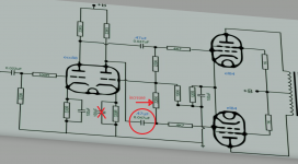
Actually, It is not feedback across four stages. The second schematic shown show a paraphase phase splitter using the two ECC88 triodes. If one look closer at the various amps at Andersons web page, you will find that the AI amps mostly used parahase phase splitters. Probably for the hi-gain allowing hi-feedback designs.
If this was my amp and I wanted to reduce gain, I would start with the following changes:
In the input stage, remove the 100uF decoupling cap.
In the splitter, I would remove the decoupling cap from (at least) the second inverter tube and also look at increasing the value of the cathode to grid feedback resistor. I would increase this to 270K, but surly someone with more experience and than me could chime in with some better advise on this.
Your coupling capasitors are shown as both 47 mF and 470mF, could you please confirm which is correct?
Since you are considering major re-design anyway, maybe the Edison12 would be a good starting point? http://www.erikasson.se/schema/edison12.gif
Feedback over four stages is quite unusual as stability is difficult to maintain, so the original circuit is strange.
You can send feedback to the cathode of the first ECC88 triode. This will then look much like most power amps.
Actually, It is not feedback across four stages. The second schematic shown show a paraphase phase splitter using the two ECC88 triodes. If one look closer at the various amps at Andersons web page, you will find that the AI amps mostly used parahase phase splitters. Probably for the hi-gain allowing hi-feedback designs.
If this was my amp and I wanted to reduce gain, I would start with the following changes:
In the input stage, remove the 100uF decoupling cap.
In the splitter, I would remove the decoupling cap from (at least) the second inverter tube and also look at increasing the value of the cathode to grid feedback resistor. I would increase this to 270K, but surly someone with more experience and than me could chime in with some better advise on this.
Your coupling capasitors are shown as both 47 mF and 470mF, could you please confirm which is correct?
Attachments
Last edited:
It is, if it is as he described. The first stage he wished to omit (shown in the first picture) is followed by the rest of the amp (shown in the second picture - which has three stages); that comes to four stages. Maybe he meant something different?LJT said:Actually, It is not feedback across four stages.
It is, if it is as he described. The first stage he wished to omit (shown in the first picture) is followed by the rest of the amp (shown in the second picture - which has three stages); that comes to four stages. Maybe he meant something different?
I stand corrected. I always considered the paraphase (with both gain and inverting anode-follower) as one stage, you consider it to be two.
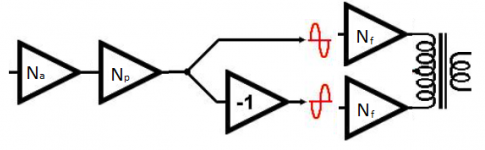
I made the attached block diagram and re-thinking I believe yours is the best way of viewing the original amp.
The inverter stage is added to one of the EL84s, but not the other. So for the "inverting" EL84 there is as you say 4 stages, while the "in-phase" see 3 stages.
Valvewizard has a nice primer on paraphase splitters. The Valve Wizard -Paraphase
Attachments
The shown paraphase is unsymmetric. Sorry.
Redo as a cathodyn where an ecc88 really works good, and where the signals are
in phase and equal.That is my suggestion.
Valvewizrds paraphase has unequal drive resistors / or a trimpot to adjust. A cathodyn
never needs adjustment.
Redo as a cathodyn where an ecc88 really works good, and where the signals are
in phase and equal.That is my suggestion.
Valvewizrds paraphase has unequal drive resistors / or a trimpot to adjust. A cathodyn
never needs adjustment.
The OP has not responded with what model amp he has, but most AI amps are PCB based. Therefore, converting to cathodyne may be difficult, however, converting the paraphase to LTP should be well within reach. The latter would effectively make this amp a variation of the mullard 5-10 variant.
This is something that I plan on doing with my own AI-800, although for various reasons I'm a bit delayed with testing and implementation. Modification paraphase to LTP.
Ketje's respons above does exactly what the OP asked for, it is a modification that removes the input stage in favor of using the paraphase gain stage serve as the input stage.
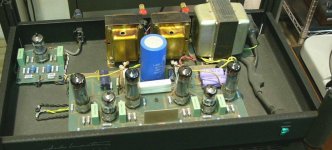
Now specifically to the amplifier in question. Unless this is an AI400 integrated amp I suspect that this amp has been victim to tube-rolling at some stage. We do not know the supply voltages, but I suspect that the input tube should have been an ECC82. In that case, no wonder gain is high. Picture below show an AI200, and input tube at left rear can be seen to be an ECC82, this corresponds with a AI200mk2 from the tables.
What do you folks think?
This is something that I plan on doing with my own AI-800, although for various reasons I'm a bit delayed with testing and implementation. Modification paraphase to LTP.
Ketje's respons above does exactly what the OP asked for, it is a modification that removes the input stage in favor of using the paraphase gain stage serve as the input stage.
Now specifically to the amplifier in question. Unless this is an AI400 integrated amp I suspect that this amp has been victim to tube-rolling at some stage. We do not know the supply voltages, but I suspect that the input tube should have been an ECC82. In that case, no wonder gain is high. Picture below show an AI200, and input tube at left rear can be seen to be an ECC82, this corresponds with a AI200mk2 from the tables.
What do you folks think?
Attachments

1. don't reduce the gain of the amp
2. don't remove the first stage
3. The easiest way of reducing the gain is by increasing feedback.
Even if there is absolutely no reason for reducing the gain, you can reduce the 4.7k resistor (feedback resistor for the input of the divider).
2. don't remove the first stage
3. The easiest way of reducing the gain is by increasing feedback.
Even if there is absolutely no reason for reducing the gain, you can reduce the 4.7k resistor (feedback resistor for the input of the divider).
I agree with petertub and lingwendil,
But the implementation depends on how much gain you need. Use a negative power supply, a current source, and a cathode coupled splitter. The second grid is connected to the negative feedback circuitry. And only use the splitter and output stages, no input stage preceding the splitter. May not have enough gain now, you might try a 12AY7. You should not need lots of volts drive for the EL84 output tubes that are high gain (pentode mode).
More negative feedback equals more possibility of instability, and more distortion of the higher order products that are created by negative feedback.
Last edited:
- Status
- This old topic is closed. If you want to reopen this topic, contact a moderator using the "Report Post" button.
- Home
- Amplifiers
- Tubes / Valves
- Audio Innovations EL84 skip 1st stage maintaining NFB