Hi,
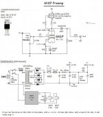
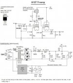
I'm presently building a MoFo power amp which doesn't have any voltage gain therefore I need a good preamp to drive it. The MoFo designer suggest a preamp with a good voltage swing and more importantly a voltage gain of about 18-20db.
I will be using the 6N1P.
The CCS is not mandatory, you could suggest a Ra value instead.
I draw the schematic with the recommended bias point (I heard that tube at that operating point and loved it) but I would need to verify if the gain on the schematic (as drawn) is within the desired 18-20db. If it's not what should be changed while staying around the same bias.
Also, what would be the best B+ to use, 300Vdc or 250Vdc or other value...
Thanks for your help and feel free to comment the schematics, I have never build a tube preamp...
Eric
Attachments
Last edited:
With a CCS plate load, you don't need as much supply voltage as you normally would need, so 250V would be plenty if only swinging a few dozen volts or so. Tune the cathode resistor value to give the desired operating point, I would shoot for 250V after filtering (and with a CCS it won't take very much) and 175-185V at the anode. Should work well and give good THD. I would leave the cathode resistor unbypassed to make the distortion primarily 2H, if you can live with the gain it provides in such a configuration.
If running a plate resistor I would go for 300V supply after filtering, and 180-195V at the anode. Bypassed cathode up to desired gain and personal preference (I prefer unbypassed if the gain is sufficient)
If running a plate resistor I would go for 300V supply after filtering, and 180-195V at the anode. Bypassed cathode up to desired gain and personal preference (I prefer unbypassed if the gain is sufficient)
Last edited:
This is a great start thanks for your time and help.
Then, if I use the CCS with a B+ of 250Vdc, 180V at the anode, Ia of 9mA, about 2.7V for Vk and I leave the cathode resistor unbypassed is there a way to predict the overall gain of the preamp ? If its too low I won't built this. Looking for 18-20db of gain.
Thanks a lot,
Eric
Then, if I use the CCS with a B+ of 250Vdc, 180V at the anode, Ia of 9mA, about 2.7V for Vk and I leave the cathode resistor unbypassed is there a way to predict the overall gain of the preamp ? If its too low I won't built this. Looking for 18-20db of gain.
Thanks a lot,
Eric
Its easy enough to simply build it and see. If gain is too low, add a cap. Easy peasy. I don't have the numbers off the top of my head, but I would think with a CCS unbypassed will give you around 20-24x gain, bypassed around 30-32... I can't convert to dB at the moment though (I'm used to working in voltages and peak for signal levels) without sitting down and doing the math.
Wow, this is plenty of gain.
I normally used this online conversation for db stuff
Decibels to Voltage Gain and Loss convert calculation conversion amplification amplifier electronics - sengpielaudio Sengpiel Berlin
Last thing, is my 50kohm volume to low, should I go with 100k ohm instead?
Thanks a lot
Eric
I normally used this online conversation for db stuff
Decibels to Voltage Gain and Loss convert calculation conversion amplification amplifier electronics - sengpielaudio Sengpiel Berlin
Last thing, is my 50kohm volume to low, should I go with 100k ohm instead?
Thanks a lot
Eric
Updated schematic + verification please
Hi,
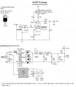
Just updated the schematic, added an input cap (0.1uF) and changed value for output cap. to 4.7uF
Can someone verify the schematic and components values and check if all makes sense.
Thank you very much,")
Eric
Hi,
Just updated the schematic, added an input cap (0.1uF) and changed value for output cap. to 4.7uF
Can someone verify the schematic and components values and check if all makes sense.
Thank you very much,
Eric
Attachments
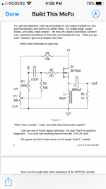
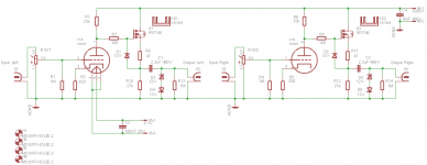
Better option would be two bottles, one per channel, with gain stage feeding cathode follower, perfect for such use. 200k input resistor with an input cap isn't too bad of a load, but it work better if you go with a cathode follower. Lower output impedance to better drive the cap without variations in frequency response.
Correction to post # 7:
The 6N1P has Transconductance of about 4400 uMhos.
The 6N1P has Plate resistance, rp of 7700 Ohms, not 4400 Ohms.
Post # 11, you beat me to it.
The 6922 and 6N1P are not the same, here is the rest of the story:
In Very Rough terms:
6N1P 6922 & 6DJ8
u 33 u 33
rp 7700 Ohms rp 2800 Ohms
Gm 4400 uMhos Gm 12000 uMhos
Yes, I know that these values are approximate, but we all get the idea.
The actual and correct formula is u = GM rp
Last edited:
Better option would be two bottles, one per channel, with gain stage feeding cathode follower, perfect for such use. 200k input resistor with an input cap isn't too bad of a load, but it work better if you go with a cathode follower. Lower output impedance to better drive the cap without variations in frequency response.
Hi,
I did intend to use 1 tube/ch.
Do you mean something like this ?
BR
Eric
Attachments
Last edited:
Bonjour Eric,
There is another possibility to have a low output impedance without the need of a second tube, just use a MOSFET source follower
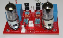
Here is an exemple of a simple preamplifier which use a 12AU7, but a 6N1P can be used with a different wiring for the heater (it has not been tesated yet)...
There is also the possibility to use a SRPP version, this is the one I am building for the EL34 Baby Huey
Regards,
Marc
There is another possibility to have a low output impedance without the need of a second tube, just use a MOSFET source follower
Here is an exemple of a simple preamplifier which use a 12AU7, but a 6N1P can be used with a different wiring for the heater (it has not been tesated yet)...
There is also the possibility to use a SRPP version, this is the one I am building for the EL34 Baby Huey
Regards,
Marc
Attachments
Hi Eric,
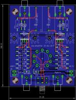
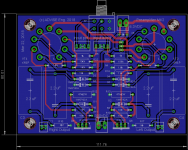
I didn't made the first one, it was just an example for a French hobbyist, but I have made PCB for the second one and I will send you one. In fact I have still the envelope that you send me with the Baby Huey Chinese PCB in March where I have your post address
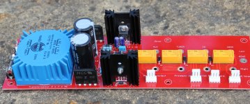
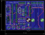
This is a part of a 3 boards preampli with relay selection, motorized volume pot and IR receiver for remote control. You can see the picture of the relay board and the layout of the processor module (not build yet)...
Hi Lingwendil,
Yes, it is a good idea, the 6CG7 or the 6FQ7 (without the shield) are compatible with the 6N1P and very similar to the 6SN7, they could give very good result, I will try them !
Best regards,
Marc
I didn't made the first one, it was just an example for a French hobbyist, but I have made PCB for the second one and I will send you one. In fact I have still the envelope that you send me with the Baby Huey Chinese PCB in March where I have your post address
This is a part of a 3 boards preampli with relay selection, motorized volume pot and IR receiver for remote control. You can see the picture of the relay board and the layout of the processor module (not build yet)...
Hi Lingwendil,
Yes, it is a good idea, the 6CG7 or the 6FQ7 (without the shield) are compatible with the 6N1P and very similar to the 6SN7, they could give very good result, I will try them !
Best regards,
Marc
Attachments
- Status
- This old topic is closed. If you want to reopen this topic, contact a moderator using the "Report Post" button.
- Home
- Amplifiers
- Tubes / Valves
- 6N1P-EV Pre-amp for MoFo