That idea (R divider from plate (down to cathode) driving a Mosfet follower) has been around. Not sure if it has actually been built. One issue would be the screen voltage getting rather low towards full output, unless a DC bias is added to it to keep that up. Likely going to limit power output otherwise. Should be optimize-able for LV Sweep tube grid 2's.
Another extension is to put the Mosfet drain current (the screen current) back into the plate circuit. Plate must stay above the grid2 then, or some kind of Cap bootstrap is needed for the Mosfet drain. (cap from drain to plate, R drain to B+ to charge the cap)
Another extension is to put the Mosfet drain current (the screen current) back into the plate circuit. Plate must stay above the grid2 then, or some kind of Cap bootstrap is needed for the Mosfet drain. (cap from drain to plate, R drain to B+ to charge the cap)
OK, if UL is essentially screen feedback why could one not simulate that mode with an untapped OPT by using a follower to set the DC screen supply voltage and to feed a portion of the plate signal into the screen of the output tube?
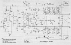
It's been done lots of times. Here's a very similar idea to make pentode finals operate like cathode followers, which will only happen if v2K is constant.
For one project, I had a junk box Stancor OPT originally designed for Class A 6L6 finals. Since the screen voltage of the 6L6 is so limited, the OPT included tertiary windings for screen feedback. Back before power MOSFETs, this was the standard way to get screen feedback without the primary UL taps when your finals couldn't operate the screen and plate at the same DC.
Attachments
Actually with UL screen taps the quiescent screen voltage is just a little bit higher than the quiescent plate voltage. That is because 60% of the primary windings have to pass the plate current (after the voltage drop from the center tap to the 40% of the primary windings that has already passed the plate + screen current). The additional 60% winding DCR x times the plate current = an additional voltage drop.
Last edited:
Hi,
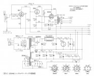
It has been some time that I strive to understand the attached schematic found in another thread. It seems to me that it's some kind of UL application, or is it? If this is the case, how do we choose the signal ratio for the screen and what is happenig when this is going too low during playback?
It has been some time that I strive to understand the attached schematic found in another thread. It seems to me that it's some kind of UL application, or is it? If this is the case, how do we choose the signal ratio for the screen and what is happenig when this is going too low during playback?
Attachments
It isn't. UL is both screen feedback and screen contributes to output. Although the former dominates, the latter cannot be ignored.mashaffer said:if UL is essentially screen feedback
That's not an UL output stage but "crazy drive" or "twin drive", i.e., with both the control grid and screen grid driven by the driver stage. smoking-amp has written quite a bit on the technique in splitting the drive voltage between the two grids.
Thanks for reply jazbo8! Although I did read smoking amp's relevant threads, I couldn't find something that could help me with the above schematic. Schematics about "crazy drive" posted at some points show g1 connected to ground and that confuses me. Perhaps you could provide a direct link?
I strive to understand the attached schematic found in another thread. It seems to me that it's some kind of UL application, or is it?.......That's not an UL output stage but "crazy drive" or "twin drive",
Or as I called it "dual drive" My version from about 8 years ago is found in posts #29 and 30 of this thread. I have been working on this concept again from a different angle, and will post it all once I fix a few more pesky issues like exploding tubes.
G1=G2/mu Scaled Drive Strawman Design
Schematics about "crazy drive" posted at some points show g1 connected to ground and that confuses me
Pure screen drive, often used with TV sweep tubes (line output) grounds G1 or ties it to a fixed potential and applies all drive to G2. Crazy / dual / twin drive feeds some portion of the drive signal to both grids.
It isn't. UL is both screen feedback and screen contributes to output.
You can use a mosfet follower to drive G2, and apply an adjustable DC voltage and an adjustable amount of the AC plate signal. You will lose the screen grid's contribution to the output power when doing this which is a small fraction of the total power output. The advantage is that you can use tapless OPT's and run UL on tubes that have a low screen grid voltage rating.
Last edited by a moderator:
One thing about UL is that the 40% screen tap is only 16% of the plate winding impedance (turns squared; 1 x 1 versus 0.4 x 0.4). For most of the signal swing, the screen current may only be about 10% of the plate current (i.e. 8 mA versus 80 mA).
It is only when the plate voltage drops far below the screen that the screen current becomes significant. Look at the Pentode family of curves that also shows the screen current on the same graph. This does not show on the UL set of curves, but it applies according to the screen voltage and plate voltage. That means you have to analyze.
Some tubes, i.e. 6L6 family have multiple sets of curves, that cover many values of screen voltage. Do a bit of analysis and predict the effect as it applies to UL.
What that means is that the power to the output resulting from the screen current (as applied to 0.16 of the winding impedance) is of very little effect until the output stage is very near to clipping (with the plate voltage far below the screen voltage as the plate 'attempts' to get real close to the cathode).
Compared to Pentode mode, the purpose to use UL is for better linearity and for lower output impedance, both are true before applying global negative feedback. The purpose of UL was not to capture more power (from the screen to the OPT).
Last edited:
Nevertheless UL does add a little screen power, and it does this when most needed: near clipping. Most 'non-tap UL' attempts either add no extra power, or consume power (e.g. in a resistive tap).
This 'can I do UL without a tap?' question comes up from time to time. Curiously, the answers stay the same.
This 'can I do UL without a tap?' question comes up from time to time. Curiously, the answers stay the same.
- Status
- This old topic is closed. If you want to reopen this topic, contact a moderator using the "Report Post" button.
- Home
- Amplifiers
- Tubes / Valves
- UL output stage without tapped xformer?