Maybe use a current limiter, like a CL120? Pete Millet uses them between the rectifier and capacitor on his engineers amplifier. I've been meaning to grab a few next time I order parts, as I have a few power hungry amplifiers planned in the future.
Just to add, my EL86 amplifier uses a 230VAC toroid into 4x1N4007 as a bridge into a 330uF cap, and from there it feeds the output tubes transformers directly, off the same cap I run a 100R/47uF RC stage into a pair of mosfet capacitance multipliers (one for the preamp/splitter stage, one for the screen voltage) and I have to problems with in rush current, going off of the PSUDII simulations and from running the amplifier with a DMM in series to test current. Next version of the amplifier will likely use parallel outputs with several pairs of 6P43P-E, and I want to use 1000uF or more capacitance, so I think an inrush limiter would be worthwhile.
Just to add, my EL86 amplifier uses a 230VAC toroid into 4x1N4007 as a bridge into a 330uF cap, and from there it feeds the output tubes transformers directly, off the same cap I run a 100R/47uF RC stage into a pair of mosfet capacitance multipliers (one for the preamp/splitter stage, one for the screen voltage) and I have to problems with in rush current, going off of the PSUDII simulations and from running the amplifier with a DMM in series to test current. Next version of the amplifier will likely use parallel outputs with several pairs of 6P43P-E, and I want to use 1000uF or more capacitance, so I think an inrush limiter would be worthwhile.
Hi. I think i will try the CL120 also") My primary power source is 12 volts dc so when the output B+ supply of 600 volts has even 1A of inrush current that translates to 50A+ at 12v. I will program an AVR cpu to measure the voltage and only after the capacitors are charged to at least 70% then a relay will connect the capacitors directly. Also the same cpu will check other voltages and drive a lcd display. I am also considering to program a stm32f4 to do real time fft and display it. Btw today after adjusting everything i managed to get 0.5% THD at 25w rms and 1.5% at 50w rms with no global feedback, with 20db global feedback i get 0.03% at 25w and 0.2 at 50w rms, all measurements at 1Khz with CCITT filter (300hz-3khz). I also tried with 300-99khz filter and there was no change, the only significant change was recorded when i allowed 50hz to creep in by using the 20hz to 99Khz filter.
My primary power source is 12 volts dc so when the output B+ supply of 600 volts has even 1A of inrush current that translates to 50A+ at 12v. I will program an AVR cpu to measure the voltage and only after the capacitors are charged to at least 70% then a relay will connect the capacitors directly. Also the same cpu will check other voltages and drive a lcd display. I am also considering to program a stm32f4 to do real time fft and display it. Btw today after adjusting everything i managed to get 0.5% THD at 25w rms and 1.5% at 50w rms with no global feedback, with 20db global feedback i get 0.03% at 25w and 0.2 at 50w rms, all measurements at 1Khz with CCITT filter (300hz-3khz). I also tried with 300-99khz filter and there was no change, the only significant change was recorded when i allowed 50hz to creep in by using the 20hz to 99Khz filter.
Chris
My primary power source is 12 volts dc so when the output B+ supply of 600 volts has even 1A of inrush current that translates to 50A+ at 12v. I will program an AVR cpu to measure the voltage and only after the capacitors are charged to at least 70% then a relay will connect the capacitors directly. Also the same cpu will check other voltages and drive a lcd display. I am also considering to program a stm32f4 to do real time fft and display it. Btw today after adjusting everything i managed to get 0.5% THD at 25w rms and 1.5% at 50w rms with no global feedback, with 20db global feedback i get 0.03% at 25w and 0.2 at 50w rms, all measurements at 1Khz with CCITT filter (300hz-3khz). I also tried with 300-99khz filter and there was no change, the only significant change was recorded when i allowed 50hz to creep in by using the 20hz to 99Khz filter. Chris
Last edited:
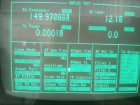
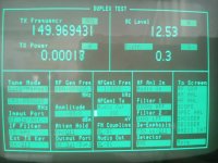
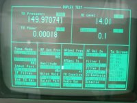
final measurements
Those are my final measurements before the actual build. The first photo is at 1Khz and 24db of global feedback (i went up to 32db with no issues) The second photo is at 1Khz and no feedback. The third photo is at 10Khz and no feedback. I selected 12 watts as a reference output because my AF generator cannot output more than 5 volts rms without distortion which are barely enough to produce 12 watts in to 4 ohm load with 24db of global negative feedback. The settings of the instrument are clearly visible. Also notice that i had to reduce the AF input from 300mv rms @ 1Khz to 200mv rms @ 10Khz in order to output the same power, with 300mv the output @ 10Khz was 25w
Chris
Attachments
Thank you for your encouraging words, i have no other means of comparing the amplifier i built other than asking the more experienced members here! It sounds so good comparing it with a JVC SS amplifier that 2 coworkers are already buying tubes etc in order to copy it, right now we are building 3 wooden frames with aluminum top sheet to be used as the amplifier's enclosure. I have done all iterations that can be done so i know that there is not much else i can do other than maybe add a 6sn7 or 6N2P tone control and preamplifier with some of the valve wizards equalizer pcb i got. I could buy it ready made but i think i like my stereo amplifier to be one piece rather than two.
Chris
Chris
You could always add a CCDA phono stage like I built into my Integrated Amp #2. Excellent sound. The 3k18 resistor is made with 3k3 and 100k in parallel.
I prefer the second schematic but it uses twice the tube count. It's based on the Aikido by Broskie, but without the Aikido mojo as I'm using switching power and don't need to inject PS noise.
The CCDA needs ~20ma, the Aikidoesque needs ~50ma.
I prefer the second schematic but it uses twice the tube count. It's based on the Aikido by Broskie, but without the Aikido mojo as I'm using switching power and don't need to inject PS noise.
The CCDA needs ~20ma, the Aikidoesque needs ~50ma.
Attachments
Last edited:
Well this is something to consider. What is considered the standard in input sensitivity for a tube amplifier for connecting it with say a cd player? I am leaning on this one in the image as i need at least 10V rms output in order to drive the amplifier with full NFB.
Chris
Chris
Attachments
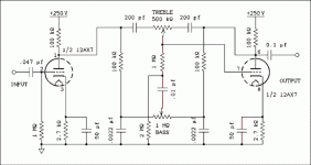
Most people would say either 0.7V or 1V for full output. This approach allows the use of a passive stepped attenuator or potentiometer right off of the CD player rather than an active gain stage. I, however prefer to use a line stage and drive the amp with 3 to 6V (the line stage will swing 20V). Either add a gain stage before the existing amp design or lower the NFB. There are better tone circuits IMHO. You also might want to try Duncan Amps' tone stack calculator. TSC
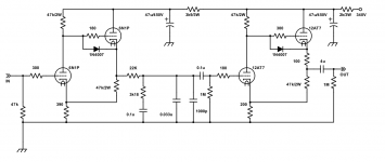
I've attached a schematic of a tone network that I've built but not installed in it's amp yet. Still if you notice the values of the parts are substantially lower resulting in less noise.
EDIT: I would use 47k resistors instead of 22k or lower the voltage to 200V but I think it will work fine as is, the tubes will run a little harder though.
Attachments
Last edited:
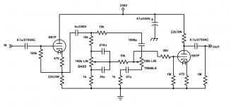
Just ordered some pcb for the PI only, the NFB circuit is enhanced and it works fine with the LED bias.
When i finish and test everything i will post the relevant files.
The Tone stack is not the final design, obviously some cleanup is needed.
Chris
When i finish and test everything i will post the relevant files.
The Tone stack is not the final design, obviously some cleanup is needed.
Chris
Attachments
Last edited:
mixed fliaments in series?
Hi. I am thinking to series-parallel mix the various tube filaments as follows: I have 4 829b's that each needs 1.125A at 12.6V and 4 6SN7GT's that i will use in a 2P2S configuration (2 in parallel and then 2 paralleled sections in series) so the whole 6SN7 block will be fed with 1200ma at 12.6V Now i will use a 12V dc boost converter with CC and CV capability and i will set the voltage to 63Volts and the current limit to 1.125A. This will allow me to elevate the concertina 6sn7 filaments to 50-60 volts since they will be the first in the chain and use one power supply for all filaments.
Any opinion on my scheme is welcomed because i cannot think why this scheme shouldn't work. With constant current i gain low inrush current but i get positive temperature coefficient and a theoretical runaway condition (in practice it cannot happen) that the voltage regulation should address and solve.
Chris
Why bother? The 6SN7 can handle -100V+200V HK voltage. Also if you elevate the heaters 60V for the phase splitter, you raise the heaters for all tubes, no?
Personally, I've never raised a heater, but I've exceeded the max voltage by at least 50V, and never had a failure. YMMV though.
Koda
Personally, I've never raised a heater, but I've exceeded the max voltage by at least 50V, and never had a failure. YMMV though.
Koda
Hi.
You are correct about heater elevation and thank you for the information about the heater limit (it is very good to know actual experimental data) but i do gain simplicity because i need only one boost converter and low current which means thinner wire and less heat, don't i?
So you think that this scheme will work as far as the filament connection scheme is concerned?
Chris
Reminder:
If you ignore the cathode to filament voltage ratings; and if the cathode is "floating/moving" as in either a true current sourced LTP, or a Concertina phase splitter, you can expect the filament to cathode to develop leakage resistance over time. That WILL affect the performance of those aforementioned circuits.
This has been discussed many times in threads on this site, but is often forgot.
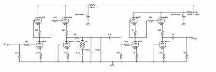
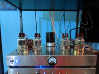
I thought I'd show you what I ended up building with some inspiration from Chris here...
I originally was going for triode connected but settled on tetrode mode. All powered by my SMPS based PSU that I use for my integrated amp.
Fixed bias, 200V screen, 440V plate, 65ma OP.
I originally was going for triode connected but settled on tetrode mode. All powered by my SMPS based PSU that I use for my integrated amp.
Fixed bias, 200V screen, 440V plate, 65ma OP.
Attachments
- Status
- This old topic is closed. If you want to reopen this topic, contact a moderator using the "Report Post" button.
- Home
- Amplifiers
- Tubes / Valves
- my first post and a question