Hi. I have been lurking for a long long time here reading anything of interest about valves because where i work i found a large (actually huge) stack of various rf and audio valves and decided to make a tube amplifier using some of those. I have at my disposal almost any equipment available for communications and audio analyzing as radio electronics quality assurance and testing is my primary field.
Also please note, i am old at 55 now and i am an electronics engineer who does read a lot. Now please don't think that i am trying to impress anyone i am just describing the situation the best i can. Anyway to make a long story short i finished constructing the preamplifier and the phase splitter (concertina with preamplifier) using the ECC84.
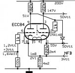
I do have loads of Telefunken E88CC, 12SN7GT, 6SN7, 12SG7, 5751 12AU7 etc but i wanted to understand the theory first by designing the circuit from scratch using not main stream tubes because i think it is better for learning. After tweaking and checking the loadlines i managed to get 41Vpp output (max undistorted 60Vpp) with 2,8Vpp input at 200v supply (i need the 200 volts for the 829b screens) which are more than enough to drive the 829b in saturation. Overall distortion was 0,2% and power stage will have two 829b per channel in AB1 Push Pull configuration, supplied with 500v.
I use SMPS all around usually operating at >50Khz so supply noise does not exists (tested). Now here is the question, before i leave for the weekend i decided to test some other ECC84 valves i got for testing repeatability and to my surprise the second tube had 0,8 distortion and lower output after warm up. Imagine looking at the audio analyser's display and seeing the sine wave getting bigger and bigger as the tube is getting warmer but at some point after it reaches the 41 volt output the amplitude is getting smaller again and it settles at about 38Vpp but with 0,8% distortion now not 0,2 as the first valve. Are tubes that much different from each other or the second tube is damaged. I am asking because the plate current is larger than the first tube with equal bias by 5%, the valve does not look tired... I will test many tubes first thing Monday but i also wanted an answer or theories from different people as my mind is always biased .
.
Chris
Also please note, i am old at 55 now and i am an electronics engineer who does read a lot. Now please don't think that i am trying to impress anyone i am just describing the situation the best i can. Anyway to make a long story short i finished constructing the preamplifier and the phase splitter (concertina with preamplifier) using the ECC84.
I do have loads of Telefunken E88CC, 12SN7GT, 6SN7, 12SG7, 5751 12AU7 etc but i wanted to understand the theory first by designing the circuit from scratch using not main stream tubes because i think it is better for learning. After tweaking and checking the loadlines i managed to get 41Vpp output (max undistorted 60Vpp) with 2,8Vpp input at 200v supply (i need the 200 volts for the 829b screens) which are more than enough to drive the 829b in saturation. Overall distortion was 0,2% and power stage will have two 829b per channel in AB1 Push Pull configuration, supplied with 500v.
I use SMPS all around usually operating at >50Khz so supply noise does not exists (tested). Now here is the question, before i leave for the weekend i decided to test some other ECC84 valves i got for testing repeatability and to my surprise the second tube had 0,8 distortion and lower output after warm up. Imagine looking at the audio analyser's display and seeing the sine wave getting bigger and bigger as the tube is getting warmer but at some point after it reaches the 41 volt output the amplitude is getting smaller again and it settles at about 38Vpp but with 0,8% distortion now not 0,2 as the first valve. Are tubes that much different from each other or the second tube is damaged. I am asking because the plate current is larger than the first tube with equal bias by 5%, the valve does not look tired... I will test many tubes first thing Monday but i also wanted an answer or theories from different people as my mind is always biased
. Chris
Paraphrasing… You
(1) Are an electrical engineer with lots of free-to-use awesome equipment due to your workplace provisioning. OK, we're all salivating! per the saying “Great job if you can get it!”
(2) Have a lot of tubes which no one apparently is holding ownership-hostage. Well… now your audience of valveheads is not just salivating, but we're starting to wriggle and bleat plaintively. The luck!
(3) Have been designing your own circuits - which is noble. Given that this is your first post, we'll give you a break for not posting a schematic. Yet. Please post the schematic corresponding the the meat of your post:
(4) Found a pair of valves that have wildly different performance - which is definitely vexing to newbie and oldster alike. That schematic? The tube? The brand(s)? You know, specifics mate.
(5) Would like the field's opinions as to why - which you've got literally hundreds of eyes and minds keen to contribute.
_______
So mate, gin up a nice 1000 × 1200 pixel copy of a schematic; make sure it has annotated the values of the parts, the measured voltages. A hand-drawn schematic is just fine!!! Post it. Maybe consider taking an oscillograph of the 'good'→'transition'→'distorted' valve's instrument reading and include in another posting. Consider it.
Yours,
GoatGuy
Hi.
Gia sou Hristo.
No it is not oscillating at least on my audio analyzer display. It warms up up to max output of 41Vpp and then the amplitude decreases to 37-38Vpp, it actually looks like overshooting and the distortion is 0,8% instead of 0.2%
As i said i will test a bunch of ecc84 Monday and report back but it is nice to have theories about what is causing it.
Chris
I suspect that this might be the problem as the plate current is actually greater than the better performing valve in contrast with gain which is lower than the "good" valve and that's why it outputs less amplitude.The change in behavior while heating can be a leak between grid+sheeld and an anode.Or starsts oscillating ones enough current, did you use grid stoppers ?
And shure, a schematic would be nice.
For now, an exaple
Mona
The puzzling thing is this "overshooting" behavior.
Chris
Nice circuit Ketje !
have you tested it?
Monday i will rewire the ECC84 as a differential amplifier with ccs at the tail and test again.
Btw i have done every possible iteration on the schematic i posted.
I have tried cathode resistors, bypassed and not, different bias voltages, different grid resistors, different anode resistors etc.
The presented circuit was tweaked to death until it performed best as far as frequency response (bandwidth), noise and THD.
Chris
Comments on schematic
(C₅ R₇) - using (Z = 1/(2πFC)), you get Z = 795 kΩ at 20 Hz. Since you have a 1 MΩ grid-to-ground resistor, that makes a (1000 / (1000 + 800)) = 0.55× voltage divider. 20log₁₀( 0.55 ) = –5 dB attenuation at 20 Hz. Working that up for various frequencies:
Unless this attenuation is what you want, I advise using a large value capacitor. 100 nF gets you –0.7 dB at 20 Hz and –0.3 dB at 45 Hz.
(C₂ R₃) - same argument. Note that the issue of attenuation is multiplicative in the scalar domain, and additive in the logarithmic dB unit system. So…
Probably not what you intended, right? Again, changing C₃ to 100 nF or 220 nF will be helpful.
(LED₁ LED₆ LED₂) seems like mixing the "LED biasing" idea with "phase inversion stage" … unique! OK. I can't see why it wouldn't work. Phase inverter is accomplished.
R₈ has an annotation error. 10 K, K?
Power Supply… as drawn has misleading values. Also missing values. C₉, C₁₀, C₇, C₈ valueless. But more importantly, the 500 VAC RMS coming into the full-wave bridge rectifier is going to have approx 500 × √(2) ≈ 700 volt peaks. I appreciate the C₇ C₈ hi-volt capacitor splitting. However, the "500 V" above C₉ is fiction at least how this is drawn up. It'd be 700 V or so. To get both power supply ripple clean-up and voltage drop (presumably what you're designing, right?) you need to have either a resistor or choke between C₁₀ and C₇; you need another resistor or choke between C₉ and C₁₀. But you do have a resistor (15 kΩ, 10 W) between the problem area and … I presume … the approx 200 V supply.
Unfortunately, the "200 volt supply" is only 200 volts quiescent, zero signal, if at all. Tube ageing, component variation, yada, yada will result in a 200±50 V at least. Maybe more when hi-signal music hits the amp. It could vary a lot in operation.
And such variations could be stimulating (not simulating) the distortion you saw per your original post. o
(C₁, R₄) (C₃, R₅) … back to exactly the same problem as the first part of this post. Because both the resistor value is scales 10× lower, AND the capacitor 10× higher, the attenuation remains the same. So now…
Again not likely what you intended during design. You probably used very low value capacitors on the basis of the much-ballyhooed theory that capacitors negatively affect sound quality. Well … ceramic 'disk' capacitors are notoriously nonlinear. Most quality capcitors are quite good. Some claim extraordinary merits. From hard-randomized X/Y[X/Y…] listening tests, I can not agree with the much repeated heresay. Good caps are transparent. And they need not be expensive.
THERE YOU ARE.
That's all I venture to do - I have to get back to work.
GoatGuy
(C₅ R₇) - using (Z = 1/(2πFC)), you get Z = 795 kΩ at 20 Hz. Since you have a 1 MΩ grid-to-ground resistor, that makes a (1000 / (1000 + 800)) = 0.55× voltage divider. 20log₁₀( 0.55 ) = –5 dB attenuation at 20 Hz. Working that up for various frequencies:
20 Hz = –5.0 dB
25 Hz = –4.3 dB
32 Hz = –3.6 dB
40 Hz = –2.9 dB
50 Hz = –2.4 dB
63 Hz = –2.0 dB
80 Hz = –1.6 dB
100 Hz = –1.3 dB
125 Hz = –1.0 dB
160 Hz = –0.8 dB
200 Hz = –0.7 dB
250 Hz = –0.5 dB
25 Hz = –4.3 dB
32 Hz = –3.6 dB
40 Hz = –2.9 dB
50 Hz = –2.4 dB
63 Hz = –2.0 dB
80 Hz = –1.6 dB
100 Hz = –1.3 dB
125 Hz = –1.0 dB
160 Hz = –0.8 dB
200 Hz = –0.7 dB
250 Hz = –0.5 dB
Unless this attenuation is what you want, I advise using a large value capacitor. 100 nF gets you –0.7 dB at 20 Hz and –0.3 dB at 45 Hz.
(C₂ R₃) - same argument. Note that the issue of attenuation is multiplicative in the scalar domain, and additive in the logarithmic dB unit system. So…
20 Hz = –5.0 dB + –5.0 dB → –10.0 dB
25 Hz = –4.3 dB + –4.3 dB → –8.6 dB
32 Hz = –3.6 dB + –3.6 dB → –7.2 dB
40 Hz = –2.9 dB + –2.9 dB → –5.8 dB
50 Hz = –2.4 dB + –2.4 dB → –4.8 dB
63 Hz = –2.0 dB + –2.0 dB → –4.0 dB
80 Hz = –1.6 dB + –1.6 dB → –3.2 dB
100 Hz = –1.3 dB + –1.3 dB → –2.6 dB
125 Hz = –1.0 dB + –1.0 dB → –2.0 dB
160 Hz = –0.8 dB + –0.8 dB → –1.6 dB
200 Hz = –0.7 dB + –0.7 dB → –1.4 dB
250 Hz = –0.5 dB + –0.5 dB → –1.0 dB
Probably not what you intended, right? Again, changing C₃ to 100 nF or 220 nF will be helpful.
(LED₁ LED₆ LED₂) seems like mixing the "LED biasing" idea with "phase inversion stage" … unique! OK. I can't see why it wouldn't work. Phase inverter is accomplished.
R₈ has an annotation error. 10 K, K?
Power Supply… as drawn has misleading values. Also missing values. C₉, C₁₀, C₇, C₈ valueless. But more importantly, the 500 VAC RMS coming into the full-wave bridge rectifier is going to have approx 500 × √(2) ≈ 700 volt peaks. I appreciate the C₇ C₈ hi-volt capacitor splitting. However, the "500 V" above C₉ is fiction at least how this is drawn up. It'd be 700 V or so. To get both power supply ripple clean-up and voltage drop (presumably what you're designing, right?) you need to have either a resistor or choke between C₁₀ and C₇; you need another resistor or choke between C₉ and C₁₀. But you do have a resistor (15 kΩ, 10 W) between the problem area and … I presume … the approx 200 V supply.
Unfortunately, the "200 volt supply" is only 200 volts quiescent, zero signal, if at all. Tube ageing, component variation, yada, yada will result in a 200±50 V at least. Maybe more when hi-signal music hits the amp. It could vary a lot in operation.
And such variations could be stimulating (not simulating) the distortion you saw per your original post. o
(C₁, R₄) (C₃, R₅) … back to exactly the same problem as the first part of this post. Because both the resistor value is scales 10× lower, AND the capacitor 10× higher, the attenuation remains the same. So now…
20 Hz = –5.0 dB + –5.0 dB + –5.0 dB → –15.0 dB
25 Hz = –4.3 dB + –4.3 dB + –4.3 dB → –12.9 dB
32 Hz = –3.6 dB + –3.6 dB + –3.6 dB → –10.8 dB
40 Hz = –2.9 dB + –2.9 dB + –2.9 dB → –8.7 dB
50 Hz = –2.4 dB + –2.4 dB + –2.4 dB → –7.2 dB
63 Hz = –2.0 dB + –2.0 dB + –2.0 dB → –6.0 dB
80 Hz = –1.6 dB + –1.6 dB + –1.6 dB → –4.8 dB
100 Hz = –1.3 dB + –1.3 dB + –1.3 dB → –3.9 dB
125 Hz = –1.0 dB + –1.0 dB + –1.0 dB → –3.0 dB
160 Hz = –0.8 dB + –0.8 dB + –0.8 dB → –2.4 dB
200 Hz = –0.7 dB + –0.7 dB + –0.7 dB → –2.1 dB
250 Hz = –0.5 dB + –0.5 dB + –0.5 dB → –1.5 dB
Again not likely what you intended during design. You probably used very low value capacitors on the basis of the much-ballyhooed theory that capacitors negatively affect sound quality. Well … ceramic 'disk' capacitors are notoriously nonlinear. Most quality capcitors are quite good. Some claim extraordinary merits. From hard-randomized X/Y[X/Y…] listening tests, I can not agree with the much repeated heresay. Good caps are transparent. And they need not be expensive.
THERE YOU ARE.
That's all I venture to do - I have to get back to work.
GoatGuy
Last edited:
Hi. I never intended to make you do all that work, i feel guilty! I will use your values of course as the capacitors are clearly the wrong values but that was not what i am after right now.
Right now i am getting acquainted with the tube operation and topology so i am building this amplifier version in order to acquire as much knowledge as i can in a short time. The schematic is far from finished as i change it every day after testing, so far the phase splitter is working fine (together with the 100k grid resistors) and its supply comes from another SMPS that outputs whatever voltage i want up to 400V.
The filament supply also comes from a buck converter, in fact the whole amplifier will work with 13,8v DC. My only concern is those 200 volts needed for the 829B screens so i opted for a 200v preamplifier supply. The 500v supply comes from an isolated full bridge smps that outputs square wave at 50Khz so the RMS equals peak, after rectification i should have 500v dc.
Chris
Last edited:
It is not grid leak, i guess the schematic is not clear, the bias is actually coming from an inverting boost converter 12vdc to -20vdc as the whole amplifier works with 13,8VDC. I will finish the schematic and post it this week in order to show the inverting boost converter. As it is now yew it contains a lot of errors like that 470 trimmer at the CCS (it should be 1Kohm).PS: I'm not sure what the floating grid-leak bias is about at the pair of output stages. It has (at least to me) always seemed like a questionable topology for power stages. Maybe i'm just an old fâhrt tho. Could be, could be! GoatGuy
Chris
Last edited:
PPS: to do the [X/Y]… testing, I built a 5 output randomizer (6502 based, in the dark ages) that had several rotary-switch selectable testing regimens. One mode just asserted ¹/₀ at random on all 5 outputs regardless of the prior test. And recorded that. Had a long cable to a "listener control" box, which allowed a person to vote on whether she liked A or B better. The music was continous and unbroken. The transitions were damped to be without annoying clicks and pops. Quite a project. Took months to perfect. Years to get results from.
Anyway, history. Welcome to the DIY world!
GoatGuy
Anyway, history. Welcome to the DIY world!
GoatGuy
Bear in mind that the ECC84 has something of a semi-remote cutoff characteristic (also known as variable mu) as it was intended for VHF TV RF amplifier use with AGC. Hence the gain you get will depend on bias point, and bias point will vary by perhaps 20-30% from sample to sample. It may also vary as the valve warms up, especially if it is a bit gassy. In some cases this will improve as the getter absorbs gas.
Hi. Good to know because the tube manual says that it is intended as an rf cascode amplifier but it does not say anything about remote cutoff. The "good" and the "bad" valve do show normal warm up behavior but the "bad" valve after warm up is finished behaves like a PID loop that has overshoot and then corrects the error.
The problem i have is that if the tube is not faulty then i find this amount of tube characteristics variation from 0,2% to 0,8% THD very annoying, if valves do have a 20-30% bias variation like you said (which i don't doubt ) then this behavior can be explained away but in any case i must think of a correction mechanism...
Thinking about it i remember that i tried with bias voltages from -1,5v to -5V and the gain was within 10% in the stage prior to the phase splitter so there must be something wrong with the valve, maybe gas as you said. I will test 5-10 more valves Monday so i can establish an average and then change the concertina to a differential amplifier with CCS in order to see if this topology is better. I only need 40Vpp (15V rms) for full output but i won't rest until i try everything
Chris
Last edited:
You have a bias balance pot for the output tubes. That does not do anything, unless one or the other tube is drawing grid current (leaky grid).
Change that circuit to have separate pots for each tube. You can see many such circuits for examples. But your schematic also does not show sense resistors in the cathode circuit. Use a 1 or 10 Ohm sense resistors in each tube's cathode. Then you can measure the voltage (and calculate the the corresponding current) in the two tubes, and can set the currents by adjusting the now corrected circuit with the two bias pots.
The ECC84 has a maximum 0.5 Meg Ohm grid rating. You are using it in both locations with a 1 Meg Ohm resistor. Changing to 500k will require re-adjusting the coupling cap sizes, that has already been discussed in the thread.
Last edited:
You are correct if there is no grid current there is nothing to be adjusted, i will correct that, it was just a quick way to finish the eagle schematic.
Funny i was thinking to incorporate a simple AVR or a STM32 MPU that will read the bias point of each tube (with a digital low pass filter of course and a simple bypass capacitor, we don't want fast corrections during operation) and adjust the bias accordingly among other things (like applying plate voltages after warm up, driving a LCD display etc.
Being almost at the end of my career gives me a lot of free time... About the grid resistors you are correct but i tested anything from 10 kilo ohm to 1Mohm and the difference was very small for grid resistors ranging from 100Kohm to 1Mohm. Fixed now as is the power tube biasing scheme.
Chris
Last edited:
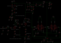
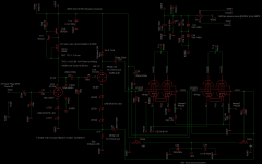
Updated schematic
Hi.
I found some time to update the schematic according to your recommendations which are correct of course! Besides the part labeling the CCS is changed to reflect the actual i used during testing (and not the one i would like to use) which will use also be used for the differential setup, it works fine with the formula 0,65/current. The values noted are actual measurements.
Chris
Attachments
- Status
- This old topic is closed. If you want to reopen this topic, contact a moderator using the "Report Post" button.
- Home
- Amplifiers
- Tubes / Valves
- my first post and a question