The difference only becomes apparent when the valve is a bit gassy or very hot (which creates the same situation). Then you can get thermal runaway if the grid resistor is too big.hendrixgr said:About the grid resistors you are correct but i tested anything from 10 kilo ohm to 1Mohm and the difference was very small for grid resistors ranging from 100Kohm to 1Mohm.
Valves have looser tolerances than semiconductors. The ancient circuit designers knew how to cope with this. They mostly avoided DC coupling, CCS, fixed bias etc. - all the things which modern audio designers seem to love.
I am a a fan of Darth VaderSorry but i find it close to unreadable , a black background and dark colors.

Let me see if i can change it....
Chris
Last edited:
Excellent!Better ?
Mona
The eagle schematic does not have many color options...
Chris
I am a a fan of Darth Vader
Let me see if i can change it....
Chris
Actually, I had no problem with the black background. It isn't the source of issues tho.
Since you're using an SMPS at 50+ kHz, you don't really need bigger than 5 μF (C₄₀ + C₄₁ = 10 μF + 10 μF series). (I was going to object, if it were a conventional 50–60 Hz transformer supply. But no objection for SMPS)
The (C₃₂ = 220 nF) you have attached to the screens … is mighty low. Oh wait… there's a (C₁₀ = 4.7 μF) too. Hmmm… you're supplying 3.1 mA to V₁A's anode, about 3.5 mA to V₁B's, and likely a few mA to the 4 pentode output sections together. Maybe more. Call it 10+ mA. Aren't flyback converters kind of light on providing mA? I remember them from the color CRT days, and you were lucky to get 50 μamp out of them. Granted, over 35 kV, but still … light. Is the +200 supply essentially rock solid regardless of source material?
I see you still have those (C₂₀ = C₂₁ = 220 nF) caps there driving the (R₃₀ = R₃₁ = 100 kΩ) bias ballast resistors. Perhaps I wasn't clear - this'll still result in LF attenuation. Maybe you're OK with it. Also C₂, R₂₀.
Z = 1/(2πFC)
atten = 20 log₁₀( R₃₀ / (R₃₀ + Z) )
atten = 20 log₁₀( R₃₀ / (R₃₀ + 1/(2πFC₂₀)) )
atten = 20 log₁₀( R₃₀ / (R₃₀ + Z) )
atten = 20 log₁₀( R₃₀ / (R₃₀ + 1/(2πFC₂₀)) )
Taking all 3 poles (C₁ R₁), (C₂ R₂₀₎, (C₂₀ R₃₀) + (C₂₁ R₃₁) into consideration:
20 Hz → –6.0 dB
25 Hz → –4.9 dB
32 Hz → –3.9 dB
40 Hz → –3.2 dB
50 Hz → –2.6 dB
63 Hz → –2.1 dB
80 Hz → –1.7 dB
100 Hz → –1.4 dB
125 Hz → –1.1 dB
160 Hz → –0.9 dB
200 Hz → –0.7 dB
25 Hz → –4.9 dB
32 Hz → –3.9 dB
40 Hz → –3.2 dB
50 Hz → –2.6 dB
63 Hz → –2.1 dB
80 Hz → –1.7 dB
100 Hz → –1.4 dB
125 Hz → –1.1 dB
160 Hz → –0.9 dB
200 Hz → –0.7 dB
IF you're OK with that, then great! (but let me know, otherwise I'll keep harping.)
Apart from that, this thing should work quite well.
Nice design, even if your schematic parts placement gives others headaches!!!
LOL
GoatGuy
PS: when I'm designing, I generally analyze all poles as above, and shoot for a –1.5 dB at 20Hz attenuation. This provides excellent "WOW" attenuation for vinyl record playback and old fashioned reel-to-reel or cassette tape recordings. Modern music which definitely stretches down to-and-below 20 Hz is not materially impacted. If you worked just with this design criterion, then all of the capacitors would be 0.47 μF, and the 100 kΩ ballast resistors changed out to 220 kΩ. Overall, –1.6 dB at 20 Hz. Leave the 470 kΩ unadjusted.
Last edited:
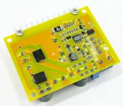
The converter i use can supply more than 200ma but i don't intend to use it beyond 120ma. It is readily available on ebay, i didn't gave it much thought so you are probably right maybe it is a regular boost converter although it looks like a flyback from the transformer configuration which in theory can provide more than 100W with no problems (taken from a book on smps design) Just look under the pcb where the transformer is soldered near the big diodes, it looks like a flyback connection with simple rectification but i didn't thought of analyzing this further. This version outputs two voltages, one up to 390v and one up to 780v (or split voltages i am not sure) that's why it has two diodes where other versions sold on ebay have only one rectification diode hence one output Here it is DC-DC Boost Converter 8-32V 12V to +-45V-390V High Voltage ZVS Capacitor Charging 4913263140856 | eBay
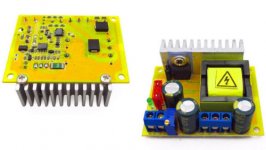
The high power one is based on SG3525 as a full bridge isolated converter. My main concern is audio performance so after i make sure that it is worth it (i am building just one channel) i will design a proper power supply but with those low prices from China it was tempting to utilize them during the testing phase.
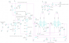
About the filter capacitors you are right there is no need for big capacitors and the only critical parameter is the capacitor ESR. Right now i am trying to decide if the ECC84 is up to the job or i must revert to E88CC. I will fix the issues with the coupling capacitors and grid resistors you pointed out as you are correct about the rc constants in the schematic, the parts placement may looks a bit strange but it looks fine to my brain Chris
The high power one is based on SG3525 as a full bridge isolated converter. My main concern is audio performance so after i make sure that it is worth it (i am building just one channel) i will design a proper power supply but with those low prices from China it was tempting to utilize them during the testing phase.
About the filter capacitors you are right there is no need for big capacitors and the only critical parameter is the capacitor ESR. Right now i am trying to decide if the ECC84 is up to the job or i must revert to E88CC. I will fix the issues with the coupling capacitors and grid resistors you pointed out as you are correct about the rc constants in the schematic, the parts placement may looks a bit strange but it looks fine to my brain
ChrisAttachments
Last edited:
I see you still have those (C₂₀ = C₂₁ = 220 nF) caps there driving the (R₃₀ = R₃₁ = 100 kΩ) bias ballast resistors. Perhaps I wasn't clear - this'll still result in LF attenuation. Maybe you're OK with it. Also C₂, R₂₀. IF you're OK with that, then great! (but let me know, otherwise I'll keep harping.) Apart from that, this thing should work quite well. Nice design, even if your schematic parts placement gives others headaches!!! LOL
I forgot to ask, is there any sound quality reason not to use an electrolytic capacitor for coupling between stages provided that the dc component is taken in to account or i need to stick with non polarized capacitors? I was thinking of using 1 or 2,2 or 4,7 microfarad non polarized capacitors rated to 400 volts (like those found in ac motors) all around for coupling but i don't know if electrolytics are suitable for this job. I have many of those non polarized capacitors at my disposal, i am just asking for the electrolytics out of curiosity.
Chris
Last edited:
I would stick to film caps. Preferably MKP (Metalized polypropylene). The motor caps are fine, too.
The ones rated X2 for SMPS are perfectly fine for coupling audio stages IMHO. Seriously. A 20 cent part can outperform a more expensive exotic "audio" capacitor.
I have used this kind of boost converter. I wouldn't use it for anything more than about 15W. I have fried them before asking it for 335V@50ma...
Consider :
DC-AC Converter 12V to 110V 200V 220V 280V 150W Inverter Boost Board Transformer | eBay
And
MINI DC-AC Inverter 12V To 18V220V/380V 500W Boost Step UP Power Module New Hot | eBay
Not adjustable but far more capable.
I've built an integrated amp using SMPS. There's a thread about it here: Ganged switching power supply for a tube amp.
Last edited:
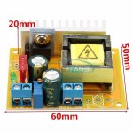
I have used these converters ( DC-DC Boost Converter 8-32V 12V to +-45V-390V High Voltage ZVS Capacitor Charging 4913263140856 | eBay)
you won't get 120mA out of it for more then a few seconds.
But it will work just fine for the preamp.
you won't get 120mA out of it for more then a few seconds.
But it will work just fine for the preamp.
Consider … https://www.mouser.com/datasheet/2/315/ABD0000C255-1131244.pdf
they're 79¢/ea, which isn't particularly outrageous. Darn good too. There are other brands, of course. Sometimes the commodity-trusted brand is where the gold is.
GoatGuy
they're 79¢/ea, which isn't particularly outrageous. Darn good too. There are other brands, of course. Sometimes the commodity-trusted brand is where the gold is.
GoatGuy
I have the 500w one and it looks nice and i will order the other one also for testing but in the end i will use something like this Power Supply Module ASTEC Aif04zpfc-02 100 | eBayI would stick to film caps. Preferably MKP (Metalized polypropylene). The motor caps are fine, too.
The ones rated X2 for SMPS are perfectly fine for coupling audio stages IMHO. Seriously. A 20 cent part can outperform a more expensive exotic "audio" capacitor.
I have used this kind of boost converter. I wouldn't use it for anything more than about 15W. I have fried them before asking it for 335V@50ma...
Consider :
DC-AC Converter 12V to 110V 200V 220V 280V 150W Inverter Boost Board Transformer | eBay
And
MINI DC-AC Inverter 12V To 18V220V/380V 500W Boost Step UP Power Module New Hot | eBay
Not adjustable but far more capable.
I've built an integrated amp using SMPS. There's a thread about it here: Ganged switching power supply for a tube amp.
or design my own as i have done in the past as i have a lot of experience designing smps especially 32 bit controlled ones.
Nice information about the capacitors, i will now go and check your design!
PS. i just had a look, what a wonderful piece of art!
I recognize most dc converter in your amplifier, i have loads of them also especially the dc buck boost ones.
Chris
Last edited:
Thanks!Consider … https://www.mouser.com/datasheet/2/315/ABD0000C255-1131244.pdf
they're 79¢/ea, which isn't particularly outrageous. Darn good too. There are other brands, of course. Sometimes the commodity-trusted brand is where the gold is.
GoatGuy
Chris
Thanks for the complement on my "IA2" Integrated amp, second editionI have the 500w one and it looks nice and i will order the other one also for testing but in the end i will use something like this Power Supply Module ASTEC Aif04zpfc-02 100 | eBay
or design my own as i have done in the past as i have a lot of experience designing smps especially 32 bit controlled ones.
Nice information about the capacitors, i will now go and check your design!
PS. i just had a look, what a wonderful piece of art!
I recognize most dc converter in your amplifier, i have loads of them also especially the dc buck boost ones.
Chris
Another alternative to the Panasonic caps the GoatGuy posted: https://www.mikroshop.ch/pdf/MEX-X2.pdf They are readily available on eBay etc.
I wish I had any formal training in electronics. Alas everything I know is self taught with the help of the online community. Sure, I had a basic electronics course in high school, but the most complex circuit we built was a "flip-flop" except that it was actually a multivibrator (9V batteries and transistors to flash LEDs). So much for accurate curriculum.
The 500W inverter is providing ~440V at almost 400ma max powered, of course, by an ATX supply (bias 320ma/4 EL34, plus screen grids) in my set up and it seems perfectly happy.
As for that link, I can't spend that much when I know these cheap DC-DC converters do just fine
Cheap and cheerful wins the race, for me, plus the listing doesn't even say what it does. I call it "Diminishing returns", but that's just my opinion, I could be wrong. Likewise, I won't be paying $200 for a coupling cap to gain 0.001% better results. Or using a $5000 power cord. No "Audiofoolery" here
Last edited:
hendrixgr,
Do not use electrolytics for coupling caps. This is a tube amp. Think Meg Ohm grids, and think leaky electrolytics.
Lots of solid state amps use electrolytics. Think non Meg Ohm Transistor Bases. I know someone who went completely through a sound studio solid state sound board, and threw out all the electrolytic coupling caps, and replaced with film caps. Good call.
By the way, there are "bipolar" electrolytics, do not use those for tube amps either.
"All generalizations have exceptions".
MKP caps. are certainly tolerable. 716P series "Orange Drops", whose construction is discrete polypropylene film dielectric/aluminum foil plates/copper leads, are better. Beyond that, other options are available, but definitely watch out for "snake oil" salesmen.
FWIW, I like a 4.7 μF. MKP bypassed (paralleled) by a 0.47 μF. 716P as the O/P coupler, when feeding the 10 Kohm IHF "standard" load.
FWIW, I like a 4.7 μF. MKP bypassed (paralleled) by a 0.47 μF. 716P as the O/P coupler, when feeding the 10 Kohm IHF "standard" load.
The 500W inverter is providing ~440V at almost 400ma max powered, of course, by an ATX supply (bias 320ma/4 EL34, plus screen grids) in my set up and it seems perfectly happy. Likewise, I won't be paying $200 for a coupling cap to gain 0.001% better results. Or using a $5000 power cord. No "Audiofoolery" here
No formal training in electronics but you made this wonderful amplifier, i know people with a university degree that still can't design and build a simple buck converter on their own or measure the Signal to Noise ratio etc, nothing else to be said... About the 500W version yes it looks very nice as it is a full bridge smps, if you can raise the ATX 's 12v to 15 then it will output about 500V (i think it is possible to do it)
For now i use a laboratory power supply so it is easy to do this but for standard operation it will need to a new transformer which is not hard to hand make or add wire to the existing core. I said about the PFC modules because i have more than enough within 10 feet from me, they can output from 320 to 390 but they are fully isolated so i can use two in series if needed. I agree that the modules are expensive and probably an overkill.
In any case the correct way is to design my own but only after i make sure that i like the outcome of my amplifier. Thank you about the capacitor information it is very useful! Finally i also agree with the "Audiofoolery" and the cost effectiveness you described, i was looking for the price of the Telefunken e88cc online and i was blown away from the prices i saw, 500 Euros for 4? Everything that has the audiophile stamp on it i avoid...
Chris
Last edited:
- Status
- This old topic is closed. If you want to reopen this topic, contact a moderator using the "Report Post" button.
- Home
- Amplifiers
- Tubes / Valves
- my first post and a question