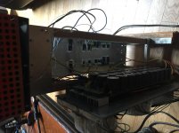
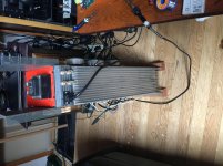
I've done a few A vs B tests with WCF vs source follower in the past and determined that the source follower sounded superior. But there were other variables at play such as different input stages so they weren't conclusive tests in the context of WCF vs source follower.
I'm building a WCF stage using 6c33c tubes for a friend but I can't help but think it is a waste of time and money. Does anyone have experience comparing SS vs tube followers?
I'm building a WCF stage using 6c33c tubes for a friend but I can't help but think it is a waste of time and money. Does anyone have experience comparing SS vs tube followers?
Member
Joined 2009
Paid Member
Using 6S33S in this manner is certainly a waste of time and money, not to mention power. Why this choice of tube?
To make a follower the best follower it can be, what you usually look for is the highest gm, which makes the active element's transfer function interfere the least with the input signal. The basis of it's operation is that a small portion of the input signal is 'wasted' between the control and output electrode (B-E, G-S, G-K, whatever...) to control the current in the active element. The less is 'wasted' the more the output will look like the input - or, in more common terms, the gain is closer to 1. What makes the 'sound' is exactly that portion that is missing to make it 1.
From that standpoint you have a huge discrepancy between even something like a 6S33S and a general purpose BJT. JFET/MOSFET are somewhere in-between, depending on which one you chose. The 6S33S has a gm of only 30mA/V and that's at huge currents. Almost any BJT will best that (and not by a little), some good JFETs will, and most but the smallest MOSFETs.
To make things worse, the 6S33S is really not the best suited for a WCF as it's mu is only about 3.
And then, another thing to consider is that all alternatives to tubes (save the rare SIT) have a pentode characteristic, so the actual transfer function (regardless of gm) can easily be very different and therefore the 'sonic stamp' resulting in using them will be different than a tube.
If you want to compare CF to WCF, than try making both using the exact same active elements. Everything else is simply not a valid comparison.
80-100ohm RP. Lowest output impedance for a tube buffer. Even less if I use it inverted. No GNFB needed. My tube math might be a bit off but I came at about 12-20 ohms output impedance in WCF config and much less in inverted mode.Why this choice of tube?
Are you saying tube followers have a noticeable "sound"? I'm building this stage for a friend that wants a "superior" version of his 6080 WCF power buffer. He insists that tube output stages have a "bigger sound stage" and might be more euphonic than SS output stages. I'm not so sure about this.And then, another thing to consider is that all alternatives to tubes (save the rare SIT) have a pentode characteristic, so the actual transfer function (regardless of gm) can easily be very different and therefore the 'sonic stamp' resulting in using them will be different than a tube.
Last edited:
...WCF vs source follower in the past and determined that the source follower sounded superior. But there were other variables at play....
The WCF is a fussy thing. Was it correctly optimized? When biased and gain-set dead-on, the THD goes to zero even for low load impedance. Get a little off the null and it can make small but complex THD.
Yes, a high current follower is dead-simple and has small euphonic THD.
I strongly suspect that glow and heat influence the listener.
For my first tests, no. The superior sonics of the source follower was clear during these tests. For my recent tests, I augmented the WCF to maintain symmetrical push-pull across all frequencies and it was a close call but my SS stage still won out.The WCF is a fussy thing. Was it correctly optimized?
My understanding of the flaws in the typical WCF is that the optimized push pull frequency range is set by the sense resistor at the anode, limiting the range of frequencies for optimal push-pull symmetry.When biased and gain-set dead-on, the THD goes to zero even for low load impedance. Get a little off the null and it can make small but complex THD.
I'm not exactly sure what your statement is alluding to though, what is this null you speak of?
Last edited:
....the sense resistor at the anode, limiting the range of frequencies for optimal push-pull symmetry....
Neither the tube nor the resistor care what frequency (up to MHz). The coupling cap from upper plate to lower grid can usually be sized to work to <1Hz. Not sure what "range of frequencies" you want.
The top plate resistor, tube Gm, and the load all interact. The top-resistor value is not obvious and good designers have done it wrong. It should be "about" 1/Gm (NOT ~~rp as sometimes done), but the optimum also depends on the loading. And the tube Mu.
Also the WCF is a feedback amplifier. It works better when the tube has good voltage gain. The big fat regulator triodes have really low gain. This is needed for large current, true. But 6080 and 6c33c may not be good WCFs. (I have not really investigated this.)
The plate resistor value in a WCF is determined by the load impedance for optimal power transfer and push-pull symmetry based on relatively complex equations that I don't remember, real world speaker impedances vary with frequency, therefore the typical WCF loses push-pull symmetry in varying degrees into a real load.
Yeah maybe but I don't know of a tube that can provide lots of gain and low output impedance. It seems like in practical use you must use a low RP tube in the linear range of its curves and take advantage of the increased output power and lower distortion that the WCF provides despite the low gain of the tubes.Also the WCF is a feedback amplifier. It works better when the tube has good voltage gain. The big fat regulator triodes have really low gain. This is needed for large current, true. But 6080 and 6c33c may not be good WCFs. (I have not really investigated this.)
Last edited:
Everything has a noticeable sound if your ears are inclined to notice things. For me tube followers have a highly noticeable and annoying sound and i never use those. But we all differ in perception.Are you saying tube followers have a noticeable "sound"?
The plate resistor value in a WCF is determined by the load impedance for optimal power transfer and push-pull symmetry based on relatively complex equations that I don't remember, real world speaker impedances vary with frequency, therefore the typical WCF loses push-pull symmetry in varying degrees into a real load.
You can find it here
https://pearl-hifi.com/06_Lit_Archi...04/Sec_19/991_White_Follower_Optimization.pdf
Yeah maybe but I don't know of a tube that can provide lots of gain and low output impedance.
Some of the bigger high-Gm RF pentodes wired in triode might give you that. Perhaps a pair of triode-wired 6J52P or 6C45P triodes would make a good WCF?
--
- Status
- This old topic is closed. If you want to reopen this topic, contact a moderator using the "Report Post" button.
- Home
- Amplifiers
- Tubes / Valves
- Source follower VS white cathode follower

