Ziffel,
Using an LM317 to self bias a tube: The tube will have the LM317's set current even if the tube is new, good, or partly worn out.
But using individual LM317s per tube in a parallel pair will only match the currents, not the voltage.
You have to measure the voltages across the 2 LM317s, and compare them to see if the tubes are matched.
Self Bias Resistors can be used instead, and you can see if the tubes are reasonably matched, both when they are new, and when they are aged, by comparing the voltage across the resistors.
With both LM317s, and self bias resistors, be sure to use individual bypass capacitors in parallel with the LM317s or resistors.
Keep in mind the maximum voltage the LM317 will see, you may have to use an LM317HV.
Keep in mind the maximum voltage the LM317 will see, you may have to use an LM317HV.
Use two more 01N100Ds in cascode over the LM317s? Or make a CCS with just the 01N100Ds?
I am using current sources in some of my amplifiers.
They consist of a high voltage NPN transistor, 3 resistors, and an LED.
It far exceeds the capability of the LM317 and LM317HV in 2 ways:
1. Much higher voltage rating
2. Much lower minimum voltage before drop out (lower burden voltage).
These current sources have a high enough impedance (compliance) for the circuits I use them in to work very well.
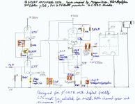
You do realize, right that the BS 107 is an enhancement mode MOSFET. It has a VON of about 2.5 volts or so. The voltage divider from reduced B+ (27 kΩ in series with 220 kΩ, 280 volt B+) lifts the gate to +30.6 V (as shown). Being enhancement mode, that implies its source pin will be about 2.5 volts less. 28.1 V.
Of course your mileage will vary.
My real problem is that the SYMBOL on the schematic is wrong. It makes the thing look like a JFET, which it decidedly is not. Enhancement mode requires something along the lines of:
http://www.learningaboutelectronics.com/images/N-channel-MOSFET.png
Just saying.
GoatGuy
The minimum burden voltage of an LM317 as a current source is specified as 3V + the 1.25V drop in the sense resistor = 4.25V.
The minimum burden voltage of a typical 1.7V LED reference and typical NPN as a current source is above the (typical) saturation voltage < ~ 0.5V + the 1.0V drop in the sense resistor = < ~ 1.5V.
Using the NPN current source for cathode(s) often does not require a negative supply.
But I like the idea of stringing many parts technologies in series.
Can't we use a larger negative supply if we use a Beam (True) Tetrode Eimac 4X150A at the bottom of the multi part current source? It requires 6.0V at 2.6A for the filament.
By the way, you should be able to see a glow inside the 4X150A, because it uses a Glass Window. But you may have to do your own socketing to see the glow. And custom sockets might not allow for maximum forced air cooling of the plate, screen, and seals.
Be prepared for the long filament warmup of 30 seconds; it is not the typical 11 second controlled warmup.
Last edited:
The minimum burden voltage of an LM317 as a current source is specified as 3V + the 1.25V drop in the sense resistor = 4.25V.
The minimum burden voltage of a typical 1.7V LED reference and typical NPN as a current source is above the (typical) saturation voltage < ~ 0.5V + the 1.0V drop in the sense resistor = < ~ 1.5V.
Using the NPN current source for cathode(s) often does not require a negative supply.
But I like the idea of stringing many parts technologies in series.
Can't we use a larger negative supply if we use a Beam (True) Tetrode Eimac 4X150A at the bottom of the multi part current source? It requires 6.0V at 2.6A for the filament.
By the way, you should be able to see a glow inside the 4X150A, because it uses a Glass Window. But you may have to do your own socketing to see the glow. And custom sockets might not allow for maximum forced air cooling of the plate, screen, and seals.
Be prepared for the long filament warmup of 30 seconds; it is not the typical 11 second controlled warmup.
You need to be careful using a negative power supply dedicated transformer. One might be tempted (I was, I did) to reference the Pentode heater to the negative power supply center tap. However this results in destroyed transformer!
Concerning the BS107, yes I agree, that's the way they draw it, not a problem for me. I know it should work this was published in a DIY French magazine. I built similar biased stages and for some reasons with tubes too the voltages are not the same but the device settles itself with the cathode feedback which needs to be accounted for.
gabdx,
I am curious about what happened to your negative power supply for the current source that did not work out for you.
Was the current source’s negative supply using a dedicated isolated secondary winding with its center tap grounded, and a full wave rectified circuit to get the negative bias? That will not work if the filament to cathode maximum voltage is exceeded.
Did you have an isolated dedicated filament supply for the current source tube that had its DC voltage held near enough to the cathode voltage of the tube that did not exceed the filament to cathode voltage rating? That should work.
Or was it a bridge rectifier across the whole secondary, and then you grounded the center tap and also grounded the bridge positive (+) out? That will not work.
I once made the mistake for a 7591 output stage in triode mode, but wired the socket for a 6L6 pin out. That sure did not work!
How about a schematic of your non-working application?
Then we can be sure to not repeat the trouble you had.
Last edited:
Yes 6A3, I will post in a new post. I will double check that I post the correct values because it required adjustments, designed without knowing the specs of the tube lol.
I can only say that it sounds 'relatively' better than the LM317 for many reasons, however the LM317 with a 6sn7 LTP driver is perfect and sufficient I wanted to try as many ways to drive higher power kt150/120 at 100watts.
It is a working application, it burned the transformer on the first schematic where I lowered the pentode filament potential, maybe it was a very stupid mistake.
Did you have an isolated dedicated filament supply for the current source tube that had its DC voltage held near enough to the cathode voltage of the tube that did not exceed the filament to cathode voltage rating? That should work.
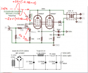
Trans: 115V to 120 (red-red) and 6V (green-green)
Rectification: Half wave around -169V, AC heaters
Connecting the heaters AC with each 100R to a high res divider with around -50V burned one of the transformer windings lol
I can only say that it sounds 'relatively' better than the LM317 for many reasons, however the LM317 with a 6sn7 LTP driver is perfect and sufficient I wanted to try as many ways to drive higher power kt150/120 at 100watts.
It is a working application, it burned the transformer on the first schematic where I lowered the pentode filament potential, maybe it was a very stupid mistake.
Did you have an isolated dedicated filament supply for the current source tube that had its DC voltage held near enough to the cathode voltage of the tube that did not exceed the filament to cathode voltage rating? That should work.
Trans: 115V to 120 (red-red) and 6V (green-green)
Rectification: Half wave around -169V, AC heaters
Connecting the heaters AC with each 100R to a high res divider with around -50V burned one of the transformer windings lol
SemperFi,
You wrote:
"Getting closer, experimental as is and something to begin with. When it's this simple it's about time to just do it. You can always build a conventional input/driver later.
But the grids should get a >+-25V drive if you want every drop of power out of the parallel twin. You have just under 4V on the FETs source, so it cannot swing more than about 20V negative."
Do you mean that I want want more or less voltage at the FET source? Do you have an estimate of what it should be?
Regarding the resistor and diode arrangement, I am just following what Koster did. I think I will use resistors for the cathodes of the 6W6GTs. I have several of these tubes so matching should not be a problem.
Thank you all for your help.
Attachments
I'd start with 40-50V on the FETs drain. Then it will be able to swing more than +-30Vp. So either reduce drain resistor value and/or reduce drain current. That leaves a little less for Vp but ballpark 225V is ok. For approx 40mA plate current grid should be about -25V. That means cathode should sit at about 65-70V. Cathode resistors need to be about 1.7kohm.
I might just build this too...
I might just build this too...
- Status
- This old topic is closed. If you want to reopen this topic, contact a moderator using the "Report Post" button.
- Home
- Amplifiers
- Tubes / Valves
- Schematic Critique – Micahel J Koster adapted for 6W6GT in PSE