Regarding having +9v on the grids? What would be a better value? +30v? Koster's 6L6GC is running +55 at the grid and +70 at the cathode. I have included a picture of his circuit.
Thank you for your help.
The tube's plate current reaches its maximum when the grid voltage is ca 0V relative to the cathode. So that's where you find peak current. Generally we have a bias that is selected for proper plate dissipation at idle (no signal), normally set to max plate rating. So to get a symmetrical signal swing up/down around the idle (no signal/bias) point, the grids are usually made to swing at least +- bias voltage. If you have 15V at the cathode at idle, you should drive the tube with at least +-15V. Since any amplifying stage is most linear around it's optimum idle/bias, and gets less linear the further away from idle the signal swings, it is often wise to design the driver to be able to swing much more than required by the tube it is driving, the idea being it will then always be within a pretty linear region.
Non of the above is possible with the ckts shown, neither Koster's or yours.
Non of the above is possible with the ckts shown, neither Koster's or yours.
The MOSFET is not capable of supplying 30V peak to the grid of the output tube? Even when run at only 4.1mA Ids, that 01N100D should still have high transconductance:
http://ixapps.ixys.com/DataSheet/DS98812E(IXTU-Y01N100).pdf
I'm using the -15V grid-cathode bias of the 5881WXT in the above question. 15Vpk signal and an additional 15Vpk for 6dB of headroom = 30V peak.
Since this is a single-ended topology, the driver stage needs to swing 15Vpk to the grid of the output stage with whatever extra for headroom, before negative feedback. The question then becomes how much more clean gain is required from the driver stage to drive the negative feedback loop from plate of output tube to grid of output tube. 6dB additional swing to drive the feedback loop? That would make 60V peak signal out needed from the MOSFET driver.
I thought depletion mode MOSFETs like DN2540 and 01N100D have lots and lots of gain available (and very high internal resistance). That gain is set by the drain load resistor, no? (R1 = 100k, needs to be a high wattage part)
It would be a lot easier to figure this using triodes with no NFB. In that case, if you have a 6L6GC in triode with -15V grid bias, you would need 15V peak output from your driver, plus another 6dB (2X) gain for headroom. Assuming a maximum of 1V peak input, you'd need 30X gain from your driver. That's achievable with a high-mu triode like 12AT7 or 6C45P, or a triode-wired 6e5P or 6EJ7/EF184. My understanding is that a DN2540 or 01N100D driver would have far too high gain if used to drive an output triode with no NFB. So where's the problem?
PS - I am ignoring the insertion loss of the OPT, though... Is that the concern?
--
Last edited:
rongon,
Concern about insertion loss of the OPT is in the eye of the beholder.
For some who build SE amps without negative feedback, and who use the tube curves to predict the output power at a reasonable or desired percent of 2nd harmonic distortion, the Output transformer insertion loss becomes a factor.
1 dB insertion loss (for many commonly used OPTs) will give 1 Watt per 1.25Watt from the output tube.
Most of the loss is caused by the DCR of the primary, and by the DCR of the secondary.
If you use that same transformer by terminating it with 1/2 of the output tap rating, you will get 2 dB loss, 1 Watt per 1.5 Watt from the output tube, due to the DCR of primary and secondary.
In addition, you will also get the drop due the heavier loading of the output tube plate resistance.
Adding negative feedback may reduce the distortion, and may increase the gain under the additional load, but it neither cancels nor makes up for the insertion power loss of the OPT
(at the same tube output power, the amp output power is less).
A 45 triode is specified for 2 Watts output. Use an OPT with 2 dB insertion loss, and get about 1.33 watts out. The 45 'guys' care about that.
By the way, if you wind a transformer with exactly a 25:1 Turns Tatio, you will not get a 5000 Ohm to 8 Ohm transformer. If you load the 8 Ohm tap with 8 Ohms, and measure the primary impedance, it will be greater than 5000 Ohms. That is because of the DCR of the primary is in series with the primary windings impedance, and the DCR of the secondary is also reflected (transformed up 25:1) back to the secondary.
6A3sUMMER,
Cool, that's good info there. However, I think that's not a huge issue when you're talking about an SE pentode amp that should make 7 or 8 watts out. If you lose two-thirds of a watt out, you're not likely to notice it. Actually the output impedance and current sinking capabilities of the amp are more likely to impact the performance when driving a loudspeaker, right? Especially considering that any loudspeaker will not present a steady resistive load to the amp. (The load impedance varies with frequency, sometimes with large changes in the low end and in the xover region.)
The question for me remains why that 01N100D can't generate enough voltage swing to drive the 6L6 or the paralleled 6W6s and the NFB loops in the circuits being discussed. The idea behind using the MOSFET was to make use of its extremely high gain (by tube standards) and high internal resistance.
--
Adding negative feedback may reduce the distortion, and may increase the gain under the additional load, but it neither cancels nor makes up for the insertion power loss of the OPT (at the same tube output power, the amp output power is less)...
By the way, if you wind a transformer with exactly a 25:1 Turns Tatio, you will not get a 5000 Ohm to 8 Ohm transformer. If you load the 8 Ohm tap with 8 Ohms, and measure the primary impedance, it will be greater than 5000 Ohms. That is because of the DCR of the primary is in series with the primary windings impedance, and the DCR of the secondary is also reflected (transformed up 25:1) back to the secondary.
Cool, that's good info there. However, I think that's not a huge issue when you're talking about an SE pentode amp that should make 7 or 8 watts out. If you lose two-thirds of a watt out, you're not likely to notice it. Actually the output impedance and current sinking capabilities of the amp are more likely to impact the performance when driving a loudspeaker, right? Especially considering that any loudspeaker will not present a steady resistive load to the amp. (The load impedance varies with frequency, sometimes with large changes in the low end and in the xover region.)
The question for me remains why that 01N100D can't generate enough voltage swing to drive the 6L6 or the paralleled 6W6s and the NFB loops in the circuits being discussed. The idea behind using the MOSFET was to make use of its extremely high gain (by tube standards) and high internal resistance.
--
ziffel,
Which of these 4 things do you most want?
Use a pair of 6W6GT Beam Power tubes.
Use a MOSFET driver.
Use DC Coupling from driver to output stage.
Have higher Output Power.
How would you rate these 4, in order of importance?
If you want power, Beam Power mode has more than Triode-wired mode.
But Beam Power mode needs to have negative feedback both for low distortion, and for a reasonable damping factor (for Hi Fi).
For example, little 6V6 Beam Power (yes, V) guitar amps do not use negative feedback, and do not care nor need to. But that is by design; it is not Hi Fi.
Beam Power tubes that are Triode-wired often do not need negative feedback, can have low distortion and reasonable damping factors. But they have less power out than in Beam Power mode.
Using Shade feedback with tubes both for the driver tube and for the output tube, has been well established, and many successful variations have been built.
Using Shade feedback with a MOSFET driver, and Beam Power output tube(s) is more difficult, as you have seen in this thread.
If the top 2 for you are 6W6GT and MOSFET driver, and you are willing to give up DC Coupling and some Output Power, you could use RC coupling, Triode-wired Beam Power tubes, and no negative feedback.
The most difficult part might be finding a MOSFET that would give the voltage swing needed, but would also not have too much gain and not have too much distortion.
Perhaps some on this thread can select an appropriate MOSFET, and could deal with the design of the MOSFET part of the circuit to get the high swing and low gain needed, since it would no longer be constrained by: DC coupling (use RC coupling), and the Shade feedback resistor that would now be removed.
rongon,
I am glad you liked the little transformer factoid.
Please look at the bottom of my post #26. Could you select a MOSFET, and design the circuit (perhaps a depletion mode MOSFET, an unbypassed source resistor, and appropriate drain resistor to give a low enough impedance to drive a pair of 6W6GTs in Triode mode (more control grid capacitance)?
Earlier in the tread it was mentioned to use a 5k:8 transformer as a 2.5k:4 transformer.
The idea of too much DCR loss in that mis-application made me comment on it.
A 1 dB loss to 8 Watts = 6.4 Watts, not too bad.
A 2 dB loss to 8 Watts = 5.33 Watts, probably a little to high of a loss.
Hi 6A3sUMMER,
My priorities are as follows,
1) Use 6W6GT.
2) Get around 8 watts if possible.
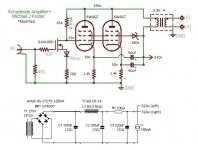
I'd really like to see if it can be done using Koster's approach. If I can't, then I'd consider replicating an alternative ciruit, such as the RH-EL84 PSE.
(RH Amplifiers: RH84 amplifier - revision 2)
Koster claims 2vrms sensitivity for his 6L6GC SE amp using the IXTP01N100D. (Tube DIY Asylum)
My priorities are as follows,
1) Use 6W6GT.
2) Get around 8 watts if possible.
I'd really like to see if it can be done using Koster's approach. If I can't, then I'd consider replicating an alternative ciruit, such as the RH-EL84 PSE.
(RH Amplifiers: RH84 amplifier - revision 2)
Koster claims 2vrms sensitivity for his 6L6GC SE amp using the IXTP01N100D. (Tube DIY Asylum)
I often run directly from a CD player or computer through a DAC.
I am also building a preamp based on Salas 6V6 circuit.
(6V6 line preamp)
I am also building a preamp based on Salas 6V6 circuit.
(6V6 line preamp)
Usually you design for 1.4 V = max amp power, going 2V doesn't account for low volume playback music which would lack amplification.
6A3s, I reach the same conclusions when 'trying to design' s.e.t. there are no magic trick and following dogmas certainly lead to failure (less stages, no feedback, save on the OT cost, not maximize power, etc.)
I just recommend against cathode bias when using // because one tube will drive all current, it is hard to find matched tubes, and even then how do you know the tubes are matched later when they age?
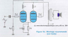
This is how to build this:
http://www.diyaudio.com/forums/attachment.php?attachmentid=676097&stc=1&d=1524166275
(c) p.59, no.371, 2012, Electroniquepratique.com
http://www.diyaudio.com/forums/attachment.php?attachmentid=676099&stc=1&d=1524166275
6A3s, I reach the same conclusions when 'trying to design' s.e.t. there are no magic trick and following dogmas certainly lead to failure (less stages, no feedback, save on the OT cost, not maximize power, etc.)
I just recommend against cathode bias when using // because one tube will drive all current, it is hard to find matched tubes, and even then how do you know the tubes are matched later when they age?
This is how to build this:
http://www.diyaudio.com/forums/attachment.php?attachmentid=676097&stc=1&d=1524166275
(c) p.59, no.371, 2012, Electroniquepratique.com
http://www.diyaudio.com/forums/attachment.php?attachmentid=676099&stc=1&d=1524166275
Attachments
gabdx,
I am glad you mentioned the CD output level issue. My players put out 2.1Vrms, and 3V peak.
But I generally do not listen to CD recordings that use high compression, and unusually high average signal levels. Those are not my kinds of music.
My CDs have lower average signal levels, and the large dynamic range requires more gain from my 2 stage amplifiers. I do not use negative feedback and for output tubes, I use DHTs, Triode, and Triode-wired Pentodes/Beam Power tubes.
I always recommend using individual separate self bias resistors and with individual bypass caps for parallel tubes. I did so earlier in this thread.
Self bias does self adjust over time, individual fixed bias pots do not self adjust. I do start with new matched tubes, and the aging match is very good.
You may be able to find a copy of "Paralleling Tubes Effects" in Glass Audio, Volume 12, Number 5, 2000 (I was one of the co-authors, doing the measurements, calculations, analysis, conclusions, hints, etc.).
It was referred to in another thread, may have been re-found in a library, or online.
It has many hints and design considerations in addition to just the individual bias issue.
The MOSFET is not capable of supplying 30V peak to the grid of the output tube? Even when run at only 4.1mA Ids, that 01N100D should still have high transconductance:
http://ixapps.ixys.com/DataSheet/DS98812E(IXTU-Y01N100).pdf
I'm using the -15V grid-cathode bias of the 5881WXT in the above question. 15Vpk signal and an additional 15Vpk for 6dB of headroom = 30V peak.
Since this is a single-ended topology, the driver stage needs to swing 15Vpk to the grid of the output stage with whatever extra for headroom, before negative feedback. The question then becomes how much more clean gain is required from the driver stage to drive the negative feedback loop from plate of output tube to grid of output tube. 6dB additional swing to drive the feedback loop? That would make 60V peak signal out needed from the MOSFET driver.
I thought depletion mode MOSFETs like DN2540 and 01N100D have lots and lots of gain available (and very high internal resistance). That gain is set by the drain load resistor, no? (R1 = 100k, needs to be a high wattage part)
It would be a lot easier to figure this using triodes with no NFB. In that case, if you have a 6L6GC in triode with -15V grid bias, you would need 15V peak output from your driver, plus another 6dB (2X) gain for headroom. Assuming a maximum of 1V peak input, you'd need 30X gain from your driver. That's achievable with a high-mu triode like 12AT7 or 6C45P, or a triode-wired 6e5P or 6EJ7/EF184. My understanding is that a DN2540 or 01N100D driver would have far too high gain if used to drive an output triode with no NFB. So where's the problem?
PS - I am ignoring the insertion loss of the OPT, though... Is that the concern?
--
Oops I take back my comment on Koster's not providing enough drive... I saw 70V on the cathode and figured out it needs +-70V drive. Of course I neglected the fact that the grid is only 15V below the cathode so it has plenty room to drive the tube. Sorry for misleading. Your ckt has 15V bias as well but cannot swing many volts negative b/c the FETs falling drain will crash into the FETs rising source.
The FET has plenty of gain but little head room.
If u can increase the voltages on the cathode and then get more available voltage for the FET to swing around then it will be fine. More voltage below cathode also reduces the effect of the temp drift of the DC coupled FET-tube.
The Drain has a note "+25V".
Can the 01N100D (or IXYS10M45) read this note?
HOW can we expect that point to be at +25V??
The datasheets do not have enough resolution at 4mA.
Of course we can trim; but trimming the 700 changes gain, the 65K both gain and NFB, and the 1Nxxx seems to be random.
At least breadboard the MOSFET part before you stick precious(?) 6W6es in there.
You may be able to find a copy of "Paralleling Tubes Effects" in Glass Audio, Volume 12, Number 5, 2000 (I was one of the co-authors, doing the measurements, calculations, analysis, conclusions, hints, etc.).
It was referred to in another thread, may have been re-found in a library, or online.
It has many hints and design considerations in addition to just the individual bias issue.
Bias individually I agree you control the idle point of the transmission.
Make the engine turn and problems arise, bias shift and one tube conduct more, the cathode potential is different in each valve when driven by a signal.
The only way to control this is to have the cathode bias individually regulated at a certain threshold (not always) when it gets stormy hehe.
You can also regulate cathode for one valve (like a precious 300B...)
I experienced tube catastrophic failures in // designs with fix bias in group of two section of the same tube, using especially different design of the SAME vintage tube.
I would need a link to read the Glass Audio, I enjoy their designs.
Koster's schematic is not fully-baked. You either have to do some breadboard experimentation to finish the design or contact him and ask how he did it. The link you shared shows that he breadboarded it. His last activity on the forum was last month, so it appears he is still around even if sporadically.
SemperFi,
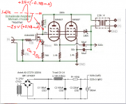
Do you mean something like this, with about 25v on the grid and 50v on the cathode?
Is that a move in a possibly useful direction?
Getting closer, experimental as is and something to begin with. When it's this simple it's about time to just do it. You can always build a conventional input/driver later.
But the grids should get a >+-25V drive if you want every drop of power out of the parallel twin. You have just under 4V on the FETs source, so it cannot swing more than about 20V negative.
BTW why the diode in series with the source? For temp stabilizing? FETs have neg tempco (up till a relatively high drain current, much higher than in this ckt). So as the FET and diode warms a little the voltage over the 700ohm source resistor will increase by about 2x2mV/C. Say they warm up 10C, you get 40mV more over 700ohms, the current goes up 57uA and grid voltage drops by 3.7V. This is in a way good b/c as the amp gets hot the tubes decrease their idle current, but this is a bit too much temp compensation. Also theres no way you will get reliable coupling between the tube's temp and the FET's temp, so no way to really depend on that to stop runnaway. ...or perhaps it is? If you like tinkering it may be fun to find out.
We're talking minute changes here (uA and mV) but with such large drain resistor (high gain) you get big changes with little effort.
I'd skip the diode and increase the source resistor. If source resistor is large enough, the few mV in FET's tempco will not matter.
Then build and experiment with getting it stable.
Also, try triode strapping the tubes.
Attachments
- Status
- This old topic is closed. If you want to reopen this topic, contact a moderator using the "Report Post" button.
- Home
- Amplifiers
- Tubes / Valves
- Schematic Critique – Micahel J Koster adapted for 6W6GT in PSE