If you want to use the essential design of schematic in post #1, I suggest the following:
Be careful when designing 300B amplifiers.
IMHO, 300Bs are expensive, they have finesse, and they should be used gently, not at their maximum ratings.
Need more power? Then use parallel single ended (learn how to implement this properly, another discussion), or use push pull.
And this applies to all 300B amps, not just post #1.
300A Maximum specs:
450V plate to filament
100mA with self bias
70mA with fixed bias
(I recommend using the 300B specs for grid resistors, as per below)
40 Watts plate
300B Maximum specs:
400V plate to filament
100mA with self bias
70mA with fixed bias
36 Watts plate
grid resistor with fixed bias 50k Ohms
grid resistor with self bias 250k Ohms
Post # 1 schematic: 1.414 x 350VAC = 495VDC - 50V rectifier drop = 445V B+, that is plenty.
And it is too much B+ for fixed bias, only a self bias circuit will get the plate to filament voltage back below 400V.
It is possible that the fixed bias tap was mis labeled at 250VAC, and could have been 50V.
But 1.414 x 50VAC is only -70V fixed bias to work with, not enough for a 300B with 445V B+
So do not use the fixed bias circuit.
Choose self bias because you have 445V B+. Remove the fixed bias circuit.
Connect a 1 k Ohm grid stopper resistor directly at the socket grid connection, and the other end to the grid leak resistor and coupling cap (As follows). Use a 180k, 150k, or 100 k Ohm grid leak resistor from the non-grid end of the grid stopper resistor, and connect the other end of the grid leak resistor to ground. Connect the coupling cap to the junction of the grid stopper resistor and the grid leak resistor.
Now, change the self bias resistor from 820 Ohms to 1k Ohms.
80mA will give 80V self bias. 445V - 80V gives 365V plate to filament, and 29 Watt plate dissipation. The current and voltage will vary some from the estimated numbers above, but will be within maximum specs; and this is a good place to start.
Be sure to use an output transformer that is rated for 80mA DC or more (100ma to be safe for up to the maximum 300B current rating), so there will not be bass distortion (and saturation which will affect mids and highs too).
artosalo,
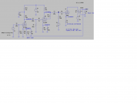
Your schematic looks pretty good.
It is a nice implementation of fixed bias.
The bias circuit will need to be modified versus the original schematic in the early post (and probably a 55, 60V tap to get the -74V with enough filtering and efficiency; 250V tap is wasteful of dropping resistor power loss).
And the B+ will need to be modified versus the original schematic in the early post (with the power transformer proposed, it will need to be modified to choke input, and an additional RC filter at the end to get enough voltage drop and enough filtering)
With a 25:1 transformer, and 3,200 Ohm primary, as shown, the output tap is 5.12 Ohms.
(The right edge of the schematic was cut off).
I did not check the 300B tube curves, but I guess if is true that 375V plate to filament (or a little less due to the OPT primary DCR and 17 Ohm sense resistor drops), and -74V fixed bias gives 79.8 mA in the 300B. That is 29.9W or slightly less plate dissipation with the aforementioned voltage drops, a pretty good combination for output power and tube life.
What output transformer or transformers do you use that is stable with the negative feedback values you have chosen?
Apparently you did not need to use a dominant pole, because there is none in the schematic.
Last edited:
I just made the simulation to see how this circuit (with slight modifications) will perform.
Therefore some circuit details are quite straightforward, like the bias circuit.
The OPT used for simulation is just an "ideal model" but contains 25 ohms primary DC resistance. However, the primary inductance (25 H) quite well determines the low frequency features of the amplifier. The high frequency end is more sketchy.
The OPT is 3k2 to 8 ohms (impedance ratio = 25/0.0625 = 400).
I let the OPT to forms the dominant pole and keep all other RCs at essentially lower frequency.
Last edited:
artosalo,
I was talking about the high frequency dominant pole of the whole amp, not the low frequency one.
The issue is the Leakage Reactance, distributed capacitances, and output transformer resonances that affect the phase versus frequency responses of the output transformer.
That can cause negative feedback to become positive feedback (oscillation).
And those phase versus frequency responses are also affected by the loudspeaker's phases and impedances versus frequency.
Perhaps some will understand that is one of the reasons why I do not go to the trouble to design and use global negative feedback. And some of the output transformers I use make the difficulty greater than a really expensive transformer would.
Maybe I am just lazy and cheap.
For output tubes, I use direct heated triodes (DHTs), indirect heated triodes, and triode wired pentode/beam power tubes.
The only 'negative feedback' circuit I use is with a current source in coupled cathode splitters. You might not recognize it as negative feedback, but it does reduce 2nd harmonic distortion.
I may get around to building an RH style amp with Shade negative feedback, but that feedback does not go around the output transformer.
I would like to find output transformers that only have 25 Ohm DCR in the primary,
but I can not afford such transformers.
Western Electric was the designer of the 300B (36 Watts plate dissipation, at least on the last original WE spec sheet).
The filament is 5 Volts at 1.2 Amps = 6 Watts
That is 42 Watts heat in the 300B envelope.
Western Electric was also the designer of the 300A. It was only that tube that was rated for 40 Watts plate dissipation.
I have used several companies modern 300B tubes. Most of them worked well, and were reliable.
However, I had one manufacturers 300B that was used at only 300V plate to filament, and only 60mA plate current (18 Watts plate dissipation). Unfortunately one of the two 300B failed, and other audio enthusiasts in my area using the same manufacturer's 300B had failures too (that manufacturer is out of business).
I have had 300B tubes from Slovakia, China, and Russia that all ran well. They did not have the problem that was mentioned above.
I have run them at more voltage, and more current, but have never used them close to the 36 Watt plate dissipation.
Last edited:
I was talking about the high frequency dominant pole of the whole amp, not the low frequency one.
The issue is the Leakage Reactance, distributed capacitances, and output transformer resonances that affect the phase versus frequency responses of the output transformer.
I have not tried to use or even seen such output transformer models that are accurate at high frequency.
I do the fine tuning process with actual prototype and with the final OPT.
tomchr,
1. I hope I remember all of the following correctly. If not, at least the essence of the information should be helpful.
I was able to talk on the phone to Charles Whitener, as well as later when I met him too.
He was able to obtain the right to use the Western Electric name for tube production, as well as manufacturing plans, notes, and material specs for many WE tubes.
He started the 300B production at Kansas City and used some of the workers from the original Kansas City WE facilities.
He later moved the operation to Georgia.
Charles also obtained the original Tungsten blob that was used to manufacture the 300B
tubes.
If I remember correctly, there are over 500 steps done in order to manufacture a WE 300B.
I don't feel that I can justify/afford to purchase the 'new" WE tubes, but boy would I like to have some of them. But in all ways, these ARE just like the original Western Electric tubes in materials, process, and performance.
2. I have listened to several manufacturers modern 300B tubes, and run all of them for hundreds of hours. And with only one exception, none of them died or measurably or listenability went bad (the company that built the bad one no longer exists).
3. I have used the JJ 300B, it is a very good tube. Yes, it does have a 40Watt plate dissipation rating.
But there is one thing that it does not have. Its filament is wired from one side of the plate to the other. That is 5V AC or DC across its total length. There are only 2 internal connections to the filament, end 1 and end 2, which are then brought out externally.
This is just a fine point, but should be noted as a difference versus the WE 300B.
All the other 300B tubes have 3 internal connections to the filament. There are 2 filaments, and they are joined in the center and connected to one of the external connections. The outside ends of the dual filament are internally connected together, and to the other external connection. The 5V AC or DC runs from one side to the center, and from the other side to the center.
And of course, all the modern 300B tubes have other differences versus the original and "Whitener" WE 300B.
Last edited:
If I remember correctly, there are over 500 steps done in order to manufacture a WE 300B.
That could be. There are many, many steps involved with the manufacturing of an integrated circuit as well. I'm not sure if that's a parameter that correlates with any perceived or measured difference in the sound quality, though.
")
I don't feel that I can justify/afford to purchase the 'new" WE tubes, but boy would I like to have some of them.
I seem to recall that they were expensive but not outrageously so by WE 300B standards. $600/pair or something. Last I casually glanced at the pricing for WE 300B tubes, I seem to recall >$1k/each.
If the WE 300B is what you want and nothing else will do, be prepared to reach for your wallet.
3. I have used the JJ 300B, it is a very good tube. Yes, it does have a 40Watt plate dissipation rating.
But there is one thing that it does not have. Its filament is wired from one side of the plate to the other. That is 5V AC or DC across its total length. There are only 2 internal connections to the filament, end 1 and end 2, which are then brought out externally.
This is just a fine point, but should be noted as a difference versus the WE 300B.
All the other 300B tubes have 3 internal connections to the filament. There are 2 filaments, and they are joined in the center and connected to one of the external connections. The outside ends of the dual filament are internally connected together, and to the other external connection. The 5V AC or DC runs from one side to the center, and from the other side to the center.
And of course, all the modern 300B tubes have other differences versus the original and "Whitener" WE 300B.
That may be. However, once an electron joins the space charge cloud it becomes indistinguishable from any other electron. Thus, I fail to see how one filament arrangement versus another should make any difference. And, yes, I am aware of marketing material that says the opposite, but to the best of by knowledge those are rooted in marketing rather than science.
I did have a Shugang (sp?) "mesh plate" (i.e. stamped perforated plate) "300B" that did a thermal runaway stunt and red-plated even at 360 V, 60-65 mA. Its 'buddy' in the "matched pair" didn't show this behaviour and ran fine even at 400 V, 85 mA as I recall. I'd bought the tubes on eBay and returned them under the buyer protection program. Seller refunded without issues.
The JJs I normally use have been rock solid. Even after about two years of daily use (probably ~1k hours) the bias still measured 85 mA. Just as it did two years prior.
Tom
tomchr,
There is noting sacred about an original tube design, that can not be changed, modified, or improved on (or made worse). But that does not make it the original.
The modern 40 Watt rated 2A3 uses a mono plate, and is a very good tube. But technically, it is not a 2A3. I have used the 40 Watt 2A3, as well as other modern 15 Watt mono plate 2A3s, and modern 15 Watt dual plate 2A3s, all the ones I used all work very well.
And of course, the original 2A3 was a mono plate, but it had far more filament runs up and down the tube than any dual plate 2A3, or any mono plate 2A3 tube today.
I had not previously mentioned the Full Music Mesh Plate 300B/n “300B” tubes that I had.
With the shiny plate structure they had, I did not expect them to get rid of heat as well as the black body radiators of so many other 300B tubes. I used the Full Music ones very conservatively, near one of the classic 300V and 60mA setups, but one of them became gassy, and useless.
I bet you could run a WE 300B at or beyond its limits without a problem.
But rather than spend the money on WE tubes, I would rather put that money into the output transformer, or toward starting another amp, etc. To each his own.
Guitar amps are often designed to exceed the maximum voltages, currents, and watts dissipation of the tubes that are in them. Is this right or wrong? It depends on what you want to achieve, and what you are willing to give up, like reliability.
Generally, the field between the cathode and grid of an indirectly heated tube tends to be more even, than the field between the grid and filament of a directly heated tube. And launched electrons behave according to electron fields.
Perhaps this does not make any difference, but I suspect it may.
All my JJ tubes that I got from eurotubes.com have been very good, and run without any problems. They go through a lot of additional testing after they arrive in the USA from the manufacturer.
Last edited:
- Status
- This old topic is closed. If you want to reopen this topic, contact a moderator using the "Report Post" button.
- Home
- Amplifiers
- Tubes / Valves
- New project 300B