Hi All
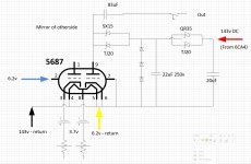
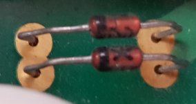
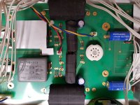
I have a preamplifier that died on me while reconnecting a cable from its power supply. Its a Hi End commercial product and about 12 years old so I have no circuit diagrams. I photographed each side of the circuit board and went about drawing it myself. I was hoping to find a match on line to aid debugging it but this is a strange one. Anyway I discovered all the diodes/zener diodes from the red input supply line to pins 1 and 9 are all short circuited, they have the codes SX15, TJ20, QR35, TJ20 but I'm unable to match them against anything so I'm unsure if they are zener or straight diodes, can anyone identify them or shed some light on the circuit operation so I might be able to take a guess?
I have a preamplifier that died on me while reconnecting a cable from its power supply. Its a Hi End commercial product and about 12 years old so I have no circuit diagrams. I photographed each side of the circuit board and went about drawing it myself. I was hoping to find a match on line to aid debugging it but this is a strange one. Anyway I discovered all the diodes/zener diodes from the red input supply line to pins 1 and 9 are all short circuited, they have the codes SX15, TJ20, QR35, TJ20 but I'm unable to match them against anything so I'm unsure if they are zener or straight diodes, can anyone identify them or shed some light on the circuit operation so I might be able to take a guess?
Attachments
So I've sent two emails so far, one to a technical address and one to general info but after 2 weeks I have yet to receive a reply. I don't wish to embarrass the manufacturer and hope to eventually get some information but you would hope for better service from a company that sales products that costs tens of thousand of pounds.
I do understand they probably want me to go through their dealer but the costs do not make sense for amplifier of this age. I will fire off an email to them but since I was not the original customer I'm not expecting much, but I also don't have much to loose!
I'm approaching retirement and wish to enjoy my equipment for many years into the future I need to be able to repair it myself so this is a good trial for what I can expect to run in to. Fortunately I'm not approaching this subject from cold since I have a degree in electronics and in my early 20s built many audio components, I admit I'm rusty but keen to re-learn and spend my retirement building tube amps and enjoying the equipment I've already purchase.
I discovered all the diodes/zener diodes from the red input supply line to pins 1 and 9
are all short circuited, they have the codes SX15, TJ20, QR35, TJ20
I'd say those are all current regulator diodes. The plate is loaded with a CCS diode (two in parallel).
The power supply regulator is a series CCS diode (two in parallel), and a shunt Zener (three in series).
In a pinch you can use appropriate resistors instead.
Last edited:
So I've sent two emails so far, one to a technical address and one to general info but after 2 weeks I have yet to receive a reply. I don't wish to embarrass the manufacturer and hope to eventually get some information but you would hope for better service from a company that sales products that costs tens of thousand of pounds.
If a manufacturer is still in business, and won't reach out to a customer that needs help in a timely manner, then they should be called out publicly.
jeff
I'll give the local dealer and manufacturer a little bit longer before naming names and burning that potential bridge.
On technical level I expect to see a first pass filter after rectification but on this amp we have a 20uf and a pair of diodes/zeners? So are we using their forward impedance as part of the filter calculation or does this confirm they must be zeners?
On technical level I expect to see a first pass filter after rectification but on this amp we have a 20uf and a pair of diodes/zeners? So are we using their forward impedance as part of the filter calculation or does this confirm they must be zeners?
I expect to see a first pass filter after rectification but on this amp we have a 20uf and a pair of diodes/zeners? So are we using their forward impedance as part of the filter calculation or does this confirm they must be zeners?
See post #5.
As Ray Ma's post you have two Zener and two Current Regulating Diode. Something like these
https://www.mouser.com/datasheet/2/362/crd-1407.pdf
These device have a 100V limit. My guess is the Zener is there to drop the voltage, so these CRDs won't blow up on power up.
I would take a meter and measure the other channel (which I suppose have not also blow up) Cathode Current and the B+ between the two set of diode. From that you can order the appropriate replacement.
Last edited:
My guess is the Zener is there to drop the voltage, so these CRDs won't blow up on power up.
The rightmost pair of series CCS, together with the shunt Zeners, form a regulated power supply.
The leftmost pair of CCS are the plate load. The two values are different. The plate load CCS is
smaller in value than the Zener CCS.
the 2 diodes connected to the plate may still be ok as there is no high current path.
83uF as the output cap? this is HUGE.
as the diodes are shorted one of them may be ok when removed from the board as the board shorts their pins together. the 3 shunts accoss the 22uF cap are likely dead, 50 - 60 volt diodes here likely.
Guess here SX15 = 1.5ma TJ20 = 2.0 ma QR35 = 3.5ma current sources
5687 has max plate current of 36ma, bias is much lower then this as diodes did not run hot
JFET "diode" current sources usually have a voltage max of 50v across them before popping
Last edited:
So thanks to all for identifying the diodes as constant current and not plain old diodes or zeners. CRD or CLD diodes are new to me, I must have been hung over during that particular lecture but now at least I understand how the voltage regulation is happening!
While researching I discovered that CRD are quite rare and expensive and made by just a few manufactures so I'll try asking them to determine if the part ids are familiar.
I shall also try and determine the three zener diode values so I can determine the voltage at that mid point in the circuit and therefore deduce the value of the CRDs.
I'll keep you all updated with my progress – thanks again for your help.
Don't want to sound like an old auntie, but this thread upsets me a bit. The Zanden is a much better preamp than 99% of the so called high-end and destroying it while trying to learn basic electronics just ain't cool. The "circuit" as drawn already speaks volumes.
Hopefully someone experienced will take pity and prevent a cruel death.
Hopefully someone experienced will take pity and prevent a cruel death.
The Zanden 3000 appears to be a Line preamp not phono preamp
you could request the parts from them first. then draw a correct schematic from the board
to ensure no mistakes are made. replacing with similar parts or resistors will work but the sound may not have the same flavour. Complicating matters, they may have matched the current diodes to provide identical currents to both plates of the tube. A transistor can replace a current diode but the exact current value must be known.
Last edited:
I still maintain that an experienced technician should mess with the repair, but could not stop myself looking at a couple of pics ")
The minimalism of the power supply just boggles the mind. Hard to tell what are the exact values of the wrapped caps but perhaps a safe upper limit judging by size and rectifier would be 47uf. As the grid bias is fixed @3.6v, a very likely operating point would be 90v, 10mA. There are no candidates for plate resistors, so load has to be another ccs. I see a (very) small chance of the tube being a follower and the ccs being at the cathode, while the voltage gain is handled by the transformers.
Used LTSpice only because i had it handy. Actual transformers are not what the circuit indicates. D4/5 is the tube rectifier after the power transformer secondary. Whatever the cc diodes are, two are connected in parallel in all locations.
Of course i may be wrong.
Attachments
Last edited:
- Status
- This old topic is closed. If you want to reopen this topic, contact a moderator using the "Report Post" button.
- Home
- Amplifiers
- Tubes / Valves
- Repairing Hi-End Preamplifier