Hi, I recently decided to enter into the tube amp field having assembled lots of chip amps, and for start I purchased a cheap Chinese preamp based on the 6n3-j Chinese tube ( equivalent 2C51/ 5670/ 6n3p), to assemble troubleshoot and of course start learning.
The link for the purchase/model is the following:
Aiyima Updated Tube Amp Preamp 6N3 Vacuum Tube PreAmplifier SRPP Board Diy Kits Fit for 5670-in Amplifier from Consumer Electronics on Aliexpress.com | Alibaba Group
Since the kit does not come with the schematic I tried to reverse engineer it.
I came up with the following attached file.
However it doesn't look very solid.
What are your opinions?
Is the 470nF on the signal input going to affect much the lower frequencies?
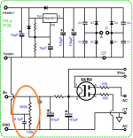
Also the recommend transformer is one with a secondary of 180V, 65mA which following rectification will go to about 250v. Isn't it to high for this kind of Tube?
Does anyone got any recommendation on the schematic and/or the power supply?
Cheers!
The link for the purchase/model is the following:
Aiyima Updated Tube Amp Preamp 6N3 Vacuum Tube PreAmplifier SRPP Board Diy Kits Fit for 5670-in Amplifier from Consumer Electronics on Aliexpress.com | Alibaba Group
Since the kit does not come with the schematic I tried to reverse engineer it.
I came up with the following attached file.
However it doesn't look very solid.
What are your opinions?
Is the 470nF on the signal input going to affect much the lower frequencies?
Also the recommend transformer is one with a secondary of 180V, 65mA which following rectification will go to about 250v. Isn't it to high for this kind of Tube?
Does anyone got any recommendation on the schematic and/or the power supply?
Cheers!
Attachments
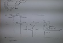
The schematic contain a number of tracing documentation mistakes. I could only guess the first stage design is a common cathode and the second stage is a cathode follower. ie. Rplate of 1st stage is missing. 1K grid stopper and input coupling cap reversed. Output coupling cap connected wrong and etc.....
Given the high input impedance, the 470nf, if anything, is on the high side. It should not effect low frequency.
250V B+ is about right for the 5670 tube
Given the high input impedance, the 470nf, if anything, is on the high side. It should not effect low frequency.
250V B+ is about right for the 5670 tube
Last edited:
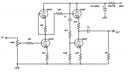
The plan *appears* to be a form of SRPP.
There are billions of variants (and boo-boos); John does not begin to get to them all in his excellent essays.
Your plan is apparently correct. I have re-drawn it in the usual way but this is equivalent to your drawing.
The 250V splits half to each triode. Each feels only about 110V. (In general, tubes never get the full supply voltage.)
Attachments
I think there must be tens of thousands of 6N3 tubes available at really cheap prices so people cook up these amps to offer something for sale cheap.
Curiosity got the better of me and I took the plunge too and bought one of these: 6N3 4pcs Audio Tube Pre-Amplifier Preamp Board Assembled Kit DIY | eBay a couple of years ago.
One of the tubes had a HUGE heater cathode leak. The B+ (~60 volts IIRC) was way too low for the tubes so they didn't draw much current. The hole thing sounded like crap.
When I traced the circuit out it was a Broskie Aikido, but a VERY poorly implemented one.
It was interesting but ultimately a waste of money. I didn't put it in a chassis and just used a couple of transformers I had kicking around to power it up so all I had in it was about 60 bucks. But it was a waste of 60 bucks.
That 60 bucks would have been far better spent buying an original Broskie board.
Cheers, Steve
kodabmx: I wasn't saying that 6N3Ps are necessarily bad. It's just that of the 4 I got only 2 were useable.
A lot of those circuits from the East just seem to be designed around the parts they have to hand, which results poor tube implementation.
The main problem I see with 6N3Ps and others in the 2C51 family is their "different" pin-out. It's more difficult to change a circuit over to 6DJ8, 6CG7 or 12AU7 etc. type pin-outs if you want to try other tubes.
Cheers, Steve
Thank you all for all the replies, I sure have a lot of reading to do about the SRPP topology and in general about valves. Broskie has defenetely a good writing style and approach.
Do you think that I should go for a higher voltage for the secondary, since 6n3p are recommended for 150V?
Cheers.
The 250V splits half to each triode. Each feels only about 110V. (In general, tubes never get the full supply voltage.)
Do you think that I should go for a higher voltage for the secondary, since 6n3p are recommended for 150V?
Cheers.
I'd start with the recommended voltage and see how it goes. Measure the power dissipated by each triode and compare to tube's specs. If it's a very small fraction (say less than 20%) of the total dissipation the unit probably won't sound very good. The tubes just won't have enough current flow to wake them up.
If at this point you want to increase the B+ be aware that it shouldn't be more than the voltage ratings of the lowest rated capacitors. The PS filter caps look to be 400 volts so you're probably OK there. The output caps look to be rated at 250 volts so the B+ shouldn't be any higher (best if it's slightly less than) 250 volts.
Good luck, Steve
- Status
- This old topic is closed. If you want to reopen this topic, contact a moderator using the "Report Post" button.
- Home
- Amplifiers
- Tubes / Valves
- Cheap Chinese 6N3P preamp, impressions and opinions