A simple comparator, comparing g1 and cathode and triggering a monoshot when g1 comes within 0.5v ( or whatever your limits are) of the cathode. The monoshot will elongate the short moment to drive a LED into visability.
Note that this won't indicate clipping, it will indicate gridcurrent. If you want to detect clipping, then similar circuits connected to the plate is needed, they will also need to detect to high and to low voltage, all at voltages > 500V thus more difficult.
Note that this won't indicate clipping, it will indicate gridcurrent. If you want to detect clipping, then similar circuits connected to the plate is needed, they will also need to detect to high and to low voltage, all at voltages > 500V thus more difficult.
As previously stated grid current does not indicate clipping. It may be the reason for clipping if the driver can not source the required grid current. In this case the clipping actually occurs in the driver and can not be detected in the output tube's plate or cathode circuit. Most tubes will perform fine when the grid is driven positive, and many will provide extra power output when doing so.
If the output tube is a pentode the screen current will abruptly rise when the plate voltage drops below the screen voltage, since it steals a larger share of the cathode current. Sensing the voltage drop across the screen grid resistor (stopper) can be a useful indicator of output tube stress. The current rise will have a sharp rise in a tube where the screen is normally operated at a voltage mush lower than the plate. A TV sweep tube with the screen at 150 volts and the plate in the 400+ volt range will draw a couple mA of screen current until clipping is reached. At this point the screen current will rise rapidly to 20 - 50 mA. A simple LED with resistor across the screen stopper can indicate clipping.
I have a little 4 watt guitar amp with the LED's mounted under the tube sockets. They remain dark until you push the amp into clipping, at which pointy they light up the tube in red with each blast on the guitar.
Long time ago, when I purchased minidsp, they gave me wrong software, and it was clipping, even the indicators on the laptop said otherwise. It was audible. So I made few simple one or two transistors circuits which indicated clipping by led diode. I applied sine wave, and set the led diode to indicate just few dB before the clipping. This way I never applied signal too high into any section of minidsp.
Later they sent me new software download, and all was good.
I can look up schematics of those indicators, if you are interested.
Later they sent me new software download, and all was good.
I can look up schematics of those indicators, if you are interested.
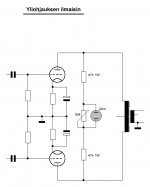
This simple circuit can indicate when a certain AC-voltage is reached/exceeded at the anodes of the output stage.
AND it has the notable steampunk idea of using a gas discharge indicator, like the commonplace NEON bulb. Remember most neon bulbs have integrated ballast resistors, so… that changes things somewhat.
Or not.
ALSO, since you have an indicator bulb not attached to ground, but only relatively powered, there's no need for voltage-divider resistors on both sides of it. One or the other side. Enough.
Also, same could be done with LEDs, but be careful: use very, very sensitive LEDs (plan on 1 ma) and understand that they become part of the audio path. Just have to change the variable resistor to a 5 kΩ device. You definitely don't want to be designing a nominal 20 ma LED into the circuit.
GoatGuy
Hmmm… OK. Again, there's value in simplicity. The NE–2 bulb is a good idea, because it is so darn cheap (and works for decades). Its not advisable to use a larger bulb. The attraction is the simplicity, and that it all works at voltages which are nominally found in valve amplifiers anyway. And its passive. Etc.
GoatGuy
GoatGuy
....If the output tube is a pentode the screen current will abruptly rise when the plate voltage drops below the screen voltage.....
That would be a tetrode.
Pentodes (and "beam power tetrodes") don't show a big rise of Ig2 when Vp falls below Vg2, because G3 tweaks the electric fields. They go tetrodey when Vp falls to some *fraction* of Vg2, typically 1/3rd to 1/10th of Vg2. This is also the "knee" of the pentode plate curve.
In hi-fi the rise of Ig2 is not a problem. Even full-power Sine drive of motors is usually well tolerated (I've rescued several large motor-amps). People who beat small tubes with big guitars do have to think about it.
Hum,
Sorry, I am not sure to understand your solution.
I don't think you meant adding LED in your screen network. But you need the LED to trigger the LDR measurement. Sorry I am confused.
Can you draw what you described?
Thanks.
Once again: imagine 2 LED-LDR pairs. LEDs connect in series, and this couple of LEDs in series connect to the trimpot. It is a screen grid current sensor. Current flows through the trimpot only, until voltage drop on it is enough to kick photons from LEDs. Photons from each LED come to own LDR. First LDR is used as a voltage divider on the input of the amp. When it is dark, the gain is maximal. But when resistance of LDR decreases, it decreases the gain.
The second LDR supplies current through a LED indicator of compression, from a filament power supply in my amps.
That would be a tetrode.
Does not matter. In pentodes screen current goes up when anode saturates. In amps with feedback (which pentode amp has no feedback?) it goes sharper. This rise is being used as an indicator of clipping approach.
An externally hosted image should be here but it was not working when we last tested it.
Last edited:
That would be a tetrode......Pentodes (and "beam power tetrodes") don't show a big rise of Ig2 when Vp falls below Vg2......In hi-fi the rise of Ig2 is not a problem.
The rise in G2 current VS plate voltage has a "knee" which is tube dependent. As the plate voltage falls toward the G2 voltage some electrons will find G2 more attractive than the plate and take an early exit there. This is primarily determined by tube geometry and to a smaller extent by G3 or the beam plates. Tubes with G2 spaced much closer to the cathode than the plate will exhibit a sharper G2 knee, but will begin to draw significant G2 current well above the knee. TV sweep tubes are a prime example. I am currently working on a design with the 6DQ6B, and screen current IS the primary power limiting factor, so I will reference those curves. G2 is usually operated in the 150 volt range, but the plate can easily be pulled down to 60 volts at G1 = 0V, lower with positive G1 voltage. At this point the screen current is around 30 mA.
If the amp is restricted to AB1 operation the grid will not pass zero volts, so G1 voltage does NOT indicate clipping. The plate voltage however is into the knee (clipping reached), or approaching it, so that the amp's distortion is already increasing. A current sensor on the screen grid current is a more reliable means of indicating true tube clipping since the tube can approach clipping without G1 current.
In hi-fi the rise of Ig2 is not a problem....People who beat small tubes with big guitars do have to think about it.
In a HiFi amp operated under HiFi listening conditions, the amp spends very little time anywhere near full power output. The average power output is usually less than 10% of rated power even if the amp is cranked to the point of clipping on loud music peaks. Someone playing bass heavy EDM into clipping, or a cranked guitar amp are exceptions, and G2 dissipation must be considered.
Even under the severe operating conditions stated above a properly designed class AB1 HiFi amp should not have an issue with G2 dissipation. I have designed most of my amplifiers in the past 10 years to be capable of A2 or AB2 operation. Screen current becomes the output power limiting factor in these designs since the plate voltage can be pulled considerably below the plate voltage and does steal a sizeable fraction of the plate current. Again this is rarely a factor in a HiFi amps, but I never know what the end user will do with one of my amps (even if the used is me), so they must be able to eat my guitar playing or be used for outdoor PA applications where the music is often so compressed that clipping isn't noticed!
Even the venerable 6L6GC can suck 40 to 45 mA of screen current in AB1 with 400 volts on the screen if the grid is driven to 0 volts. The plate is saturated at 340 mA or so if pulled to 100 volts. I would prefer to operate the same tube with 200 to 250 volts on the screen and allow G1 to go positive. With 250 volts on the screen I can hit 80 volts on the plate at +20 volts G1. The screen current is 20 mA for 5 watts of screen power and the G1 current is 50 mA for 1 watt of G1 power. Here no specs are busted, the plate hits 80 volts at 360 mA or so for a bit more power output potential, and it can eat guitar playing without melting a screen grid. Most tubes do not have a G1 dissipation spec, so a careful trade off between G1 and G2 dissipation is performed, and G2 current limitation is needed when the capability to "beat small tubes with big guitars" is desired........
I currently have a guitar amp running that extracts 35 watts at 3.5% THD in AB2 from a pair of 6AQ5's. Screen dissipation limits the continuous sine wave output at 35 watts, peaks hit 40 before the simple RC limiter brings the G2 voltage down reducing power to 35 watts. Plate voltage is 400 volts, G2 is 200 volts below 35 watts out, dropping as low as 150 when thrashed into hard clipping. Load impedance is 6600 ohms. The plate dissipation reaches 14.5 watts at 15 watts out where it levels off, and drops when thrashes into hard clipping. Some of these conditions are well above the published ratings yet no red plating or grid glow is observed even after hours of continuous sine wave at 35 watts out.
I can squeeze even more power from a pair of lowly 50C5 radio tubes on 450 volts plate and 105 volts G2, but full torture testing is not complete yet.
- Status
- This old topic is closed. If you want to reopen this topic, contact a moderator using the "Report Post" button.
- Home
- Amplifiers
- Tubes / Valves
- Clip indicator