What do you suggest for 15mA?
In my 801 preamp I use J310.
Ale sent me boards with BF862, but I didn't have time to try it.
If the output impedance is critical (for example less than one-two hundred Ohm), as far as possible use bigger forward transconductance (gFS) FET as "lower" FET in gyrator.
Last edited:
Well, I had a go at the tedious math of the output impedance during my lunch break.
Zout from the mu output can be approximated to Rmu/(1+Rmu*gfs) unless I screwed up the formulae.
This makes sense as when gfs*Rmu>>1 then it converges to 1/gfs
I’m scratching my head when I did a simulation in the past. I measured on Spice about 715R of output impedance with an Rmu of 470R. I measured gfs of 35mS for an idle current of 10mA. This is about 27R according to the formula above.
Also when Rmu converges to 0, so should Zout. Assuming gfs is maximum at this point as VGS=0.
Can someone do the maths as well to check this?
I’m tired after a long day so I made have done some mistakes down the line of playing with the formulae.
Ale
Well, I ran a quick test with Spice using a BF862 lower device. The formula works well if Rp (anode resistance) is zero. Otherwise when Rp isn't zero, I can see a difference of a factor of (Rp/Rmu+1). Need to review the formulae again as it seems like the Zo is:
Zo=Rmu/(1+Rmu*gfs)*(Rp/Rmu+1)
When you have lower devices like BSH111BK or BSN20BK that have 400mS at 30mA (measured), the impact of Rp in the output impedance is very low. For example if we have a 4P1L in triode (1600R as Rp) then the output impedance should be about 11R.
Would be great if someone plays with Spice to check the above")
Zo=Rmu/(1+Rmu*gfs)*(Rp/Rmu+1)
When you have lower devices like BSH111BK or BSN20BK that have 400mS at 30mA (measured), the impact of Rp in the output impedance is very low. For example if we have a 4P1L in triode (1600R as Rp) then the output impedance should be about 11R.
Would be great if someone plays with Spice to check the above
Well, I ran a quick test with Spice using a BF862 lower device. The formula works well if Rp (anode resistance) is zero. Otherwise when Rp isn't zero, I can see a difference of a factor of (Rp/Rmu+1). Need to review the formulae again as it seems like the Zo is:
Zo=Rmu/(1+Rmu*gfs)*(Rp/Rmu+1)
When you have lower devices like BSH111BK or BSN20BK that have 400mS at 30mA (measured), the impact of Rp in the output impedance is very low. For example if we have a 4P1L in triode (1600R as Rp) then the output impedance should be about 11R.
Would be great if someone plays with Spice to check the above
Can you provide us with a bit more context? How about a drawing of the circuit you looked at? With the schematic in post 66 I'd expect to see two different gfs values corresponding to the two FETs.
Thanks Rajko for the data, I remember seeing Michael's post long time ago.
He also explains is a complex formula and the terms are in line with what I derived.
It doesn't need to be exact as gfs varies a lot from FET to FET sample. With an approximation it would do.
In summary, for a large Rmu:
Zout=Rs/(1+Rmu*gfs) or approximately 1/gfs (like a source follower)
When Rp (anode resistance) is much bigger than Rmu:
Zout = Rmu/(1+Rmu*gfs)*(Rp/Rmu+1) = (Rp+Rmu)/(1+Rmu*gfs)
which means that Rp is added in series to the Rmu before the bootstrapping effect of the lower jFET.
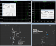
Attached is an example with the BF862 at 3mA using an Rmu of 100R and an anode impedance of 1K.
You can do your maths and see that matches the simulation
He also explains is a complex formula and the terms are in line with what I derived.
It doesn't need to be exact as gfs varies a lot from FET to FET sample. With an approximation it would do.
In summary, for a large Rmu:
Zout=Rs/(1+Rmu*gfs) or approximately 1/gfs (like a source follower)
When Rp (anode resistance) is much bigger than Rmu:
Zout = Rmu/(1+Rmu*gfs)*(Rp/Rmu+1) = (Rp+Rmu)/(1+Rmu*gfs)
which means that Rp is added in series to the Rmu before the bootstrapping effect of the lower jFET.
Attached is an example with the BF862 at 3mA using an Rmu of 100R and an anode impedance of 1K.
You can do your maths and see that matches the simulation
Attachments
Now it's clear, thank you Ale.
Next days I expect your boards.
Good, I'm glad we got to the bottom of it. I've been running around for a long time without sitting down and look at the output impedance of the hybrid mu-follower in more detail.
When you get the boards, try to measure some of this
Ale, try AOT1N60 as "lower" FET in gyrator.
gFS: 900mS !!!
Hi Bela, you need to look at the gfs at the operating current and VDS<2V.
For the AOT1N60 you get 200mS, not 900mS which is the gfs at 650mA.
I rather use the BSH111BK/BSN20BK which both can do 400mS at 30mA! These are my lower devices by choice in a cascoded pair when very low noise isn't the requirements. Otherwise I will use the BF862 in a low noise application (e.g. Phono).
For any driver stage, I think BSH111BK/BSN20BK are the best I found so far (and the sound really nice as well)
cheers
Ale
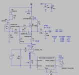
Ok, let's take this back on topic. Here's an updated schematic taking into account the recent discussion about the active load for the driver tube, and the driver tube itself.
I added the "CCS load with controlled DC voltage" to the driver stage (I refuse to call it a gyrator). Note that I left the DN2540 as the lower MOSFET for now, because this part has more than enough headroom to allow more current, has high transconductance (gfs), and is a through-hole part that is easy to solder (changing the design to use a different part should be easy if desired).
I have changed the driver tube to 6H30, which is also very linear but can be biased to provide more headroom for large input signal swings from the source without going to grid current drive. This time I did not parallel the two triode sections because I think the driver stage is strong enough to drive the 45 as it is. A single 6H30 double triode could be used for a stereo amplifier.
As before, a loudspeaker version of this design would require a different output transformer (5k primary to 8R secondary or so), but everything else should work the same.
Comments, suggestions, ideas?
Loops, I forgot the attachment. Here it is.
Attachments
That will ruin the HF response by providing a lower impedance path to the mu output. Very low current to bias zener with 1M and zener noise goes straight to the gate.
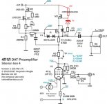
Best is to apply Walt Jung's bias multiplier:


I'd rather use the IXTP03N100D which has the best VGS out there:

Cheers
Ale
Best is to apply Walt Jung's bias multiplier:
I'd rather use the IXTP03N100D which has the best VGS out there:
Cheers
Ale
Last edited:
Ooops, I forgot the attachment. Here it is.
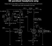
Looks good. Actually if you have strong feeling against the gyrator name, which we all agree it's not the appropriate name, I'd suggest you call it by its proper name given the topology: hybrid mu-follower
I'd suggest the following changes:
1. Ditch the battery bias and put a 180R resistor. You'd get a nice improvement and remove the batteries!
2. The DN2540 has only 200mS at 30mA. If you don't want to put any SMD device here, the AOT1N60 has slightly better gfs and smaller Crss which will improve the overall HF response.
3. I'd replace the top DN2540 for an IXT03N100D - that will make a big difference by providing proper bias of the lower device.
4. Not sure you need such voltage headroom in the driver as you will be running headphones and unlikely to go above 150-200mW?
Alternatively, the D3a is a sterling valve which will perform really well here if you are seeking for +200Vpp output swing:

N.B. cathode resistor should read 240R not 240K
Cheers
Ale
Looks good. Actually if you have strong feeling against the gyrator name, which we all agree it's not the appropriate name, I'd suggest you call it by its proper name given the topology: hybrid mu-follower
Well, maybe. But the way I understand the mu stage does not implement the controlled voltage part. Wavebourn suggested "Stable Voltage Current Source (SVCS)". Whatever.
I'd suggest the following changes:
1. Ditch the battery bias and put a 180R resistor. You'd get a nice improvement and remove the batteries!
Yes, a resistor would work very well (and it would provide some local feedback). Let's say I am just in the battery mood at the moment.
2. The DN2540 has only 200mS at 30mA. If you don't want to put any SMD device here, the AOT1N60 has slightly better gfs and smaller Crss which will improve the overall HF response.
Nice!
3. I'd replace the top DN2540 for an IXT03N100D - that will make a big difference by providing proper bias of the lower device.
I don't get it -- how and why will that be better?
4. Not sure you need such voltage headroom in the driver as you will be running headphones and unlikely to go above 150-200mW?
See previous discussion (around post 83). The D3a is indeed very nice, and you're right that the input signal amplitude will be quite small for 200 mW or so. However, I'd like to keep the flexibility to make this a "speaker amplifier". In addition, with 130 V plate voltage or so I'd have to bias the D3a at approximately Vgk = -1 V. This is already smells like grid current with no input signal at all.
- Home
- Amplifiers
- Tubes / Valves
- 45 amp build direct coupled