I am planning out the wiring for a 300B amp kit I'm going to start soon.
As far as reducing potential for hum I take it that while I might have success with elevating the 6C6 driver heater voltage, that scheme won't work on the 300B. In addition to the usual twisting and careful placement of the wires, I was thinking of passing the heater wire through some grounded copper braid once twisted.
1) Opinions pro or con?
It was also suggested to screen the input wires.
Could one just pass the pair through some appropriately sized braid or would something like this mil-spec shielded twisted pair?
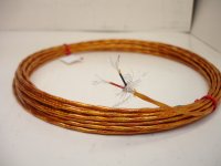
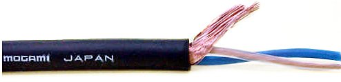
How about the Mogami microphone/console cable?
Coax such as RG-174 was also mentioned but then a parallel non-twisted scheme for the inputs would be needed.
Would one be preferable over the other?
Opinions please.
As far as reducing potential for hum I take it that while I might have success with elevating the 6C6 driver heater voltage, that scheme won't work on the 300B. In addition to the usual twisting and careful placement of the wires, I was thinking of passing the heater wire through some grounded copper braid once twisted.
1) Opinions pro or con?
It was also suggested to screen the input wires.
Could one just pass the pair through some appropriately sized braid or would something like this mil-spec shielded twisted pair?
How about the Mogami microphone/console cable?
Coax such as RG-174 was also mentioned but then a parallel non-twisted scheme for the inputs would be needed.
Would one be preferable over the other?
Opinions please.
Attachments
Last edited:
Good to be thinking ahead about these things. You mentioned it was a 300B kit? I would think the seller has the layout properly worked out all ready. But I'd add, if you do something like shielding the heater wires, best to do it ahead of the build rather than retrofit it. As for signal wire shielding, I'm assuming since you mention 6C6 as the driver, this is not balanced (could be wrong of course), I try to put the RCA input jack close enough to the first stage that internal wiring isn't critical. That being said, the 6C6 grid is via a top cap, right? In a similar 300B amp I built, I did use shielded wire to the top cap - it was helpful in removing a bit of hum.
Is your input balanced or unbalanced? Choose the appropriate internal cable: twisted pair, or shielded single.
Screening/shielding of AC heater wiring is rarely needed, provided that good construction techniques are used.
Input will be unbalanced so which one is recommended? I can do:
1) Twisted pair
2) Twisted pair within shield (grounded at one end only)
2a) Which cable might you recommend?
1-Placed inside a separate copper braided shield
2-The Mil-spec orange stuff
3-The Mogami microphone cable
4-Something else
5) The RG-174
Is there any downside to the screening of the AC heater wiring other than cost?
Thanks for the help.
Good to be thinking ahead about these things. You mentioned it was a 300B kit? I would think the seller has the layout properly worked out all ready. But I'd add, if you do something like shielding the heater wires, best to do it ahead of the build rather than retrofit it. As for signal wire shielding, I'm assuming since you mention 6C6 as the driver, this is not balanced (could be wrong of course), I try to put the RCA input jack close enough to the first stage that internal wiring isn't critical. That being said, the 6C6 grid is via a top cap, right? In a similar 300B amp I built, I did use shielded wire to the top cap - it was helpful in removing a bit of hum.
The kit is not a step-by-step build. Has general instructions and parts. The input jack should be just a couple of inches from the 6C6 tube. So maybe short non-twisted lengths of something like the R-174 would be fine.
What shielded wire did you use for the top cap?
Input will be unbalanced so which one is recommended? I can do:
1) Twisted pair
2) Twisted pair within shield (grounded at one end only)
2a) Which cable might you recommend?
1-Placed inside a separate copper braided shield
2-The Mil-spec orange stuff
3-The Mogami microphone cable
4-Something else
5) The RG–174
Is there any downside to the screening of the AC heater wiring other than cost?
Thanks for the help.
I know this will sound a bit pedantic, but the point of quoting another post is first and foremost, to read the post and understand it. In this case DF96 has already answered your multipoint list of design possibilities.
To be clear: You have unbalanced input criteria. You should use shielded single-inner-conductor “coax” cable therefore. You do not need to use super special cable either, just competent braided-shield flexible coax. You do not need to worry about coax intrinsic impedance (e.g. “75 Ω” or “50 Ω” or “90 Ω”) because audio frequency wavelength is far, far, far longer than any dimension inside the chassis of your creation.
Personally - and I'm sure others will echo this - I would stay far away from coax that uses an aluminized plastic foil shield, even if it has a ground-return wire. It cannot be soldered to, and it tends to be mechanically “difficult”: doesn't bend without kinking, that kind of thing. In your design future, you also won't use more than a hundred feet of braided coax a year. Probably far, far less. So, one hank of it will do. Its helpful if you choose a small diameter variety as well, such as ( Belden 9201 RG-58/U Coaxial Cable 20 AWG Conductor Bare Copper Braid Shield 52 Ohm 100 ft. USA )
50¢/foot. Buy a hundred, and work with it. Nice investment.
Sorry for the lecture.
I'm having a headache-Monday.
GoatGuy
Why?I was thinking of passing the heater wire through some grounded copper braid once twisted.
Most times I use enough (for 300B 1..1.2mm) thick teflon jacketed, tightly twisted wires, and never noticed hum...if the inner layout (never put signal wires near to transformers) of amp was correct.
I never used screened wires in my power or pre amps. Twist it tight, and use proper layout.It was also suggested to screen the input wires.
My #26 preamp has wooden frame, without metal bottom plate, and it perfectly humless....but I always use two box (amp and power, 1-1.5m umbilical) arrangement.
I use -for decades- Mogami cables -mostly four wire quad Neglex-.How about the Mogami microphone/console cable?
IMHO it's one of the best....for studio, where the sources and loads are has correct impedances (600R).
It has a bit highish capacitance (lower than most boutique cable, but higher than imagined), so using as interconnect or -for example- half meter input wire, the music would be a little bit "rounded".
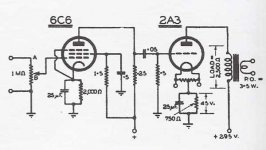
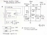
A schematic of your kit would be helpful to us.
Be sure to keep lots of space between the Power Transformer, B+ Choke, and Output Transformer (and any other 'magnetics', like an Interstage Transformer).
And have all those 'magnetics' with different orientations of the coils, i.e. one at North-South, one at East-West, and one at Up-Down relative to each other (actual compass directions are not important, I just used that for easy explanation). That is 90 Degrees from one to the other.
Do not use a Steel chassis, that destroys the trouble you take to space and properly orient all the 'magnetics'.
The only exception is Stainless Steel of the non-magnetic kind.
I Have built some 300B single ended amps with DC on the 300B filaments.
They had 300uV (0.3mV) hum. I did not take the effort and trouble to reduce the hum below 300uV, because I use loudspeakers that are only up to about 92dB/watt, and also because I do not use Headphones.
I did not have to use shielded cables to get the hum down to 300uV.
But be careful if you do use shielded cable. 2 feet of RG58 (50 Ohm coax) has 60pF.
RG59 (75 Ohm) is 40pf for 2 feet, and 90 ohm coax is less capacitance than the others.
But these coax are stiff and have big diameters. Careful, some thinner audio shielded coax has even more capacitance per foot.
Suppose you use a 100k Ohm potentiometer at the input and 2 feet of RG58 to connect from the potentiometer tap to the grid stopper resistor, with the other end of the stopper resistor to the input tube grid.
That 60pF will cause the frequency response to be -1dB at 26.5kHz, when the pot tap is set at 50kOhms (1/2 of the input signal voltage).
That -1 dB is before you have other high frequency rolloffs in the amp due to Miller capacitance, and the output transformer, etc.
Because of the Miller capacitance of the input tube, I use 50k potentiometers, I do not use 100k potentiometers.
Take a triode with 1.5pf of grid to plate capacitance, and a gain of 40, the Miller capacitance is 60pF.
Last edited:
As I said (post 3) use shielded single for unbalanced. Inside a metal chassis you can also get away with twisted, but shielded is the correct solution. Twisted may have a minor advantage if your source is poorly engineered with a high output impedance, as it could have less capacitance than shielded. Ordinary thin flexible coax is fine, with copper inner and shield.WntrMute2 said:Input will be unbalanced so which one is recommended?
Two mistakes:6A3sUMMER said:Suppose you use a 100k Ohm potentiometer at the input and 2 feet of RG58 to connect from the potentiometer tap to the grid stopper resistor, with the other end of the stopper resistor to the input tube grid.
That 60pF will cause the frequency response to be -1dB at 26.5kHz, when the pot tap is set at 50kOhms (1/2 of the input signal voltage).
60pF and 50k gives corner of 53kHz, not 26.5kHz.
Half voltage from a 100k pot gives 25k source resistance, not 50k, so the corner is actually at 106kHz.
DF96,
You are Correct.
Take a signal source of 0 Ohms (50 Ohms if you prefer). Use it to drive two 50k Ohm resistors in series to ground. At the junction of the two 50k Ohm resistors, you have about 25k Ohms.
Now, Take a signal source of unknown impedance. Use it to drive two 50k Ohm resistors in series to ground. At the junction of the two 50k Ohm resistors, you have up to 50k Ohms.
Yes, you do not want to drive the amp input with a Very high impedance signal source, but I have seen some people try (very few signal sources are Very high impedance, but I have seen some).
Just a study of limits.
A source with an output impedance which was large compared with 50k would be seriously incompetent, even by 'high end' standards. More realistic would be to assume a source impedance in the range 0-10k; if you then assume the worst (10k) you get a mid point impedance of 27.5k. In any likely case, 60pF of wire capacitance will not do much harm to HF performance. And 2ft of wiring is unlikely unless the layout is unusual.
By the way, try to take a look at other builds to see how they're laid out. This one below is the now very old Audio Note stereo 300b kit - you can see the under chassis layout very well. If you're doing mono blocks - take a look at the photos for their 300 Legend amp.
ANK Audiokits - Kit1 2014 300B Integrated or Power Tube Amplifier
ANK Audiokits - Kit1 2014 300B Integrated or Power Tube Amplifier
DF96,
Correct!
Most high impedance sources of the old days are already gone.
I do still see amp circuits that use 1Meg Ohm potentiometers at the input, which Does give a high frequency loss with the miller effect of most of the tubes they are connected to
(the volume control also becomes a tone control).
Correct!
Most high impedance sources of the old days are already gone.
I do still see amp circuits that use 1Meg Ohm potentiometers at the input, which Does give a high frequency loss with the miller effect of most of the tubes they are connected to
(the volume control also becomes a tone control).
Is your input balanced or unbalanced? Choose the appropriate internal cable: twisted pair, or shielded single.
Screening/shielding of AC heater wiring is rarely needed, provided that good construction techniques are used.
Sorry DF96. The fact that your first clause of the first sentence seemed to be asking a question and the second clause seemed to offer either of the two general types of wiring I was asking about made it confusing to me. Thanks for the clarification.
I still wonder if shielding the heater wires would do any harm.
I still wonder if shielding the heater wires would do any harm.
Probably not worth the effort, especially as the shielding will do nothing against the magnetic component which is the main problem. At worse a shield could just add shorting hazards within the amp unless you then insulate on top of that, which then possibly reduces the current carrying capacity of your heater wiring (it can no longer effectively radiate heat, admittedly if the wire is well within its ratings this is a bit of an unlikely problem scenario). Just twist the heater wires tight (but not TOO tight as to stress the insulation) and route sensibly.
These wires you posted are both unsuited to tube amps because they are stranded, you should use solid wiring if sound quality is your target; some lazy builders like stranded wire because it is easy to solder.I am planning out the wiring for a 300B amp kit I'm going to start soon.
As far as reducing potential for hum
Would one be preferable over the other?
Opinions please.
Stranded wiring create verdigris corrosion upon air and electric tension circulating.
You dont need use expensive hi quality Teflon UPOCC
But this cheap Solid UPOCC PVC awg 16 will outlast you and offer great sound quality and safety:
Neotech Solid UPOCC Copper in PVC 16 AWG Yellow, Sonic Craft

Last edited:
- Status
- This old topic is closed. If you want to reopen this topic, contact a moderator using the "Report Post" button.
- Home
- Design & Build
- Parts
- Another Wiring Question