Hello guys, I´m building stereo pushpull tube amp. I´m from Czech Republic and I´m 14 years old, please sorry for my english.
I´m using long-tailed-pair type phase inverter with tube 6N1P.
The schematic:
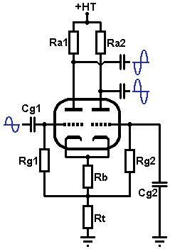
Values: Ra1, Ra2: 100k
Rg1, Rg2: 2M2
Rb: 1.5K
Rt: 47k
Capacitors: 33nF
Anode voltage: 250V.
Main two problems are:
1. Balance - one output is 15% smaller than another (this is not very big problem, i can change anode resistors to get equal amplitudes)
2. Limitation. I play the music, amp is giving about 5W of power. Than I raise the volume and amp is distorting. It makes square wawe from sinewave. When I was troubleshooting the amp, I found that this distortion isn´t producing power stage, but long tailed pair. Can you please help me, what can I do? I tried to low the anode resistor to 22k, this was bad idea. On grids was 13 volts instead of biasing -0.5 to -1.5 volts. Than I tried to change coupling capacitor. No difference. Can you please help me? Thank you very much.
I´m using long-tailed-pair type phase inverter with tube 6N1P.
The schematic:
Values: Ra1, Ra2: 100k
Rg1, Rg2: 2M2
Rb: 1.5K
Rt: 47k
Capacitors: 33nF
Anode voltage: 250V.
Main two problems are:
1. Balance - one output is 15% smaller than another (this is not very big problem, i can change anode resistors to get equal amplitudes)
2. Limitation. I play the music, amp is giving about 5W of power. Than I raise the volume and amp is distorting. It makes square wawe from sinewave. When I was troubleshooting the amp, I found that this distortion isn´t producing power stage, but long tailed pair. Can you please help me, what can I do? I tried to low the anode resistor to 22k, this was bad idea. On grids was 13 volts instead of biasing -0.5 to -1.5 volts. Than I tried to change coupling capacitor. No difference. Can you please help me? Thank you very much.
Last edited:

Limitation. I play the music, amp is giving about 5W of power.
Than I raise the volume and amp is distorting.
You are doing really great so far. If your B+ is limited to 250VDC,
then you could try lowering the value of Rt to around 10k or 15k.
It's normal for a long tailed pair like this to have unequal output voltages.
If you had balanced inputs (to both grids), then the outputs would be equal
(if the tubes are similar), due to the symmetry.
Last edited:
Replace the tail resistor with a constant current source, or increase the tail resistor and B+... As mentioned, the LTP will not provide balanced output voltage without either balanced input signals, or a very high tail load, or creative use of unequal plate resistors.
Alternatively, you could rearrange the circuit into a concertina phase splitter, this will give you perfect balance (so long as the load resistors are matched) and higher gain. You will have less output swing potential, but it's a bit better way to go without making the LTP more complicated.
Alternatively, you could rearrange the circuit into a concertina phase splitter, this will give you perfect balance (so long as the load resistors are matched) and higher gain. You will have less output swing potential, but it's a bit better way to go without making the LTP more complicated.
Using a pair of triodes with low plate resistance will deliver more voltage output. A pair of pentodes, with g2 voltage matched well to the load will improve that. It is quite possible to just run a single pair of pentodes, with a current regulator to a small negative rail( headroom for the CCS to work in ), that will let you build a two stage amp.
cheers,
Douglas
cheers,
Douglas
...amp is giving about 5W of power. Than I raise the volume and amp is distorting.
Need to know the output stage. If it needs 90V of drive, of course the driver will strain or fail.
...On grids was 13 volts instead of biasing -0.5 to -1.5 volts...
You can't directly measure the voltage at these grids. The meter loading will collapse the bias. Try it: one meter on cathodes, then poke another meter at a grid. The cathode voltage falls when 2nd meter loads a grid.
Measure plates and cathodes. Those points will be solid-enough for DMM loading, and tell all you really need to know.
If it was a 12AX7, the cathode resistor would be 470-680 not 1.5K. You may be over-biasing (not enough current). The plate+cathode voltage readings will tell.
Yes, you usually run 100K + 82K plate loads for better balance. But I don't think that is an urgent problem.
You need to pass a little bit of current through the 6N1P and some voltage across it. I chose around 3mA for each triode and 100V across the anode and cathode. You can push your B+ to 300V as long as the anode to cathode doesn't see much over 250V during operation as the tail resistor will eat (drop) quite a bit of voltage across it...
You didn't specify what output tubes you plan on driving with this.
You didn't specify what output tubes you plan on driving with this.
Attachments
BTW: Cg1 and CG2 do two different things and typically will not be the same value.
Rg1 is bootstrapped by the tail and acts-like maybe 10X its value. Cg1 could be as small as 0.001uFd and give full bass.
Cg2 has to hold the far grid at ZERO. Any signal here leaked through Rg2 cancels bass. A typical value, even for guitar, is 0.1uFd.
This is not your midrange clipping but will affect bass distortion and power.
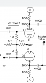
So, can you solved? I have the same problem with a 12ax7
My B+ is 290v
Pin 6 = 288v
Pin 8,3 = 55v
Pin 1 = 170v
Mabe by the tube is bad?
A couple of things to keep in mind about this LTP...
Matched plate resistors..matched tube halves..matched everything will not provide balance... Look at the equations for this circuit and it is evident.. Without feed-back you would need to use a trim pot to balance it... This circuit does very job of balancing when Feed-Back is injected into the tail.... The Feed-Back will provide a "Boot-strap" effect and raise the impedance of the tail, thus better coupling of the Phase Inverter... The Feed-Back will also provide Error Correction to any imbalance, within reason of course... I typically will balance the PI with the FB disconnected, then connect the FB.. This way the poor tube and FB are not totally cocked side-ways trying to correct a major imbalance and running out of steam... The first halve of the tube is where the Phase Inversion takes place...like a Concertina Phase Inverter... The cathode follower side is thus driving the second halve which is a Non-Inverting Grounded Grid amplifier, which is a AC Grounded Grid... The AC signal currents sum as Differential in the tail...that why the 1st stage has gain... Change the 47K to 42K .....Then break the ground point and put in a 4.7K from that node to ground ..inject FB at that node...
Last edited:
A resistor that does not return to a high negative voltage does not make a very good current sink.
Use an extremely high impedance Real current Sink in the common cathode invertor.
Then use Equal plate load resistors.
This is as balanced as a simple and straightforward phase invertor can get.
It works, because:
Current follows rules. No Electrons get lost, unless it is a Nuclear Event.
In the case of a Nuclear Event . . . well . . .
You will not be listening to your stereo.
If you do not get enough voltage swing from that kind of phase invertor, then a very good solution is to follow the phase invertor with
a pair of balanced amplifiers. Then that added stage will have enough voltage to drive the output stage.
"You should make things as simple as possible, but no simpler" - Albert Einstein
Last edited:
You can use a 5K or 10K potentiometer (1 Watt), connect the outer leads to the anode resistors and the center connector to the B+ for this stage. You can then look for a sweetspot, using a spectral display to see how harmonics (2nd, 3rd, etc.) increase and decrease. And of course don’t for get to listen with your ears!
Regards, Gerrit
Regards, Gerrit
An LTP works best with large tail resistor. 47k is sufficient, but you need to drive some 1 to 4 mA through it (depending on the tube). This means the bottom end has to be connected to a negative voltage of -50 to -200 V. If that is not feasible, use a constant current source, set for 1 to 4 mA. A CCS could work from lower voltage.
- Home
- Amplifiers
- Tubes / Valves
- Problem with Long Tailed Pair phase inverter