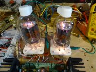
Ah No, both of those big tubies (and the other TV Sweeps) are indirectly heated.
Two 701A might keep the house warm in winter though. Like 4 big Sweep tubes in a bottle.
Heater 8V 7.5 Amps. Those tube pins are like 5/16 inch diam. Tube info here:
http://www.diyaudio.com/forums/tubes-valves/319902-tubes-radio-transmitting-tower-4.html#post5371521
Two 701A might keep the house warm in winter though. Like 4 big Sweep tubes in a bottle.
Heater 8V 7.5 Amps. Those tube pins are like 5/16 inch diam. Tube info here:
http://www.diyaudio.com/forums/tubes-valves/319902-tubes-radio-transmitting-tower-4.html#post5371521
Last edited:
In those 701A tube pictures, I can only see 4 obvious pins on the bottom, which if true, would require the cathode to be connected to a heater pin. Need to find a base diagram for those tubes to find out what they did there. I guess it doesn't make a whole lot of difference, if the heater winding is floating anyway. They do have oxide cathodes for sure. And the WE350A tube was indirect heated.
Those KT150s are going to look wimpy next to these giants with welding cable pins.
Those KT150s are going to look wimpy next to these giants with welding cable pins.
Last edited:
")
I don't think you will have a hum problem from the heaters as long as the heater winding is floating. (and not connected to other small signal tubes) The cathodes have metal sleeves below the oxide. I wouldn't use a toroid xfmr for the heater supply. (too much line noise feed-thru) Use an E-I xfmr with a ground shield between primary and secondary.
Last edited:
Ebay: 4D32 $25 50 Watt 300 mA DC, weird socket & plate cap
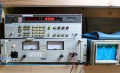
The sockets and plate caps are standard items. I got mine from ESRC. You can see me squeezing 202 watts from a pair here.
The power supply shows 650 volts at half an amp for a 200 watt sine wave output. Unless you like to listen to continuous sine waves for long periods of time, the power supply can be a bit smaller with a decent cap to handle transients.
Attachments
Last edited:
I didn't see any DC current spec in the data for the WE701A tube, so I've done some scaling from the WE350B datasheet (1949) and also from the 6CD6 tube (1949).
The WE701A is using 50% more heater power -per tube section- than the WE350B (apparently it was scaled up some from the WE350A). So working out a linear scaling from the WE350B heater data would give 3/4 Ampere DC for the full WE701A.
The 6CD6 was a near contemporary tube (RCA 1949), and the DC cathode rating scales exactly the same way versus heater power. Fully in agreement.
So 0.75 Amp DC appears to be the correct DC rating for the 701A. (12 Amp peak for pulse rating)
Two of them for 200 Watts then giving a 1.5 Amp DC rating.
The last TV Sweeps developed (1972) had improved cathodes, with about 3X the DC cathode Amps per heater Watt rating. 6LF6 providing 500 mA DC for 2 Amps at 6.3 VAC heater.
.
Last edited:
I suppose"squeezing" 200w out of them regularly isn't a good idea... I wonder how they would perform in place of KT150s?
The efficiency peaked at 200 watts out, then dropped as I went to 250 watts. Even at 250 W the tubes showed no signs of duress, but the recommended operating conditions show 125 watts of audio output.
I have never seen a KT150 since I tend to avoid high priced tubes. I have no idea how much they put out, or how far you could push them.
Most music, even highly compressed EDM has at least 10 db peak to average ratio. This means that the average power is 1/10 of the maximum power or less. Hitting 200 watt peaks occasionally while playing music at the 20 watt average level is not the same as cranking out 200 watt sine waves continuously. The power supply and the output tube's plate dissipation ratings do not need to be sized for 200 continuous watts. The peak current handling capability of both DO need to be rated for 200 watts.
I designed a 125 WPC version of Pete Millett's 18 WPC Engineers Amplifier. I replaced his 15 watt dissipation tubes with 24 watt tubes. At least a dozen copies were built with no reports of failure. Mine still uses the original set of tubes despite some long, loud listening sessions. It even stood up to me playing guitar through it, and using it for a rock band's PA system cranked to the edge of clipping outdoors.
So you are saying the power supply and regulator could be designed with a similar peak to average ratio power capability as the amplifier then.
What ratio would be satisfactory (non stalling) for music? Seems like most of the historical commercial tube amplifiers have been designed for less than a 10 to 1 ratio. Maybe 2 to 1? Some statistical analysis seems required, since the average ratio does not rule out periodic or occasional exceptions to the avg. rule.
I think the peak to avg. design ratio will work out to some statistical prediction of how long between stalls. (when the extended peak requirement temporarily exceeds the peak design rule) Maybe OK as long as the amplifier just continues to operate with some momentary over-heating. (but the music does -not- drop out!)
For a regulator, one could put a parallel Mosfet regulator channel that only carries current when the tube channel is over-loaded. So this would be tube operation 99% of the time say. Plenty of supply capacitors will help of course.
A thermostatically controlled fan could come on when the power xfmr gets too hot.
Last edited:
... 10 to 1 ratio. Maybe 2 to 1?...
Push-pull tube amps for "hi-fi", we don't idle stone-cold for reason of crossover distortion. The idle DC power may be 1/4 to 1/2 of the full-sine-tone DC power.
The clean speech/music average might be 1/10th but the power demand will be the higher idle current.
It is very likely you could run unclipped speech/music all day with steady DC only half of the test-tone max, as long as you had a large cap (500-1000uFd here) to cover the peaks. I never feel confident knowing that an amp sags when I try to burn the paint off the dummy load, but millions of saggy amps don't hardly sag in hi-fi use. (My last large tube amps, a bit bigger than proposed here, were doing large outdoor shows, so I beat them harder than I would for "nice" music.)
The efficiency peaked at 200 watts out, then dropped as I went to 250 watts. Even at 250 W the tubes showed no signs of duress, but the recommended operating conditions show 125 watts of audio output.
I have never seen a KT150 since I tend to avoid high priced tubes. I have no idea how much they put out, or how far you could push them.
I may attempt running 4D32 output tubes then. KT150s are the KT88s big brother. They can push 200w per pair. Unfortunately they are shaped like eggs, and I'm not a fan of anything but the 200w capability. So long as the 4D32 can handle the high screen voltages of ultra linear, I don't see why not.
It is very likely you could run unclipped speech/music all day with steady DC only half of the test-tone max, as long as you had a large cap (500-1000uFd here) to cover the peaks.
I won't have that large of a cap, so I'll just size the supply for continuous test-tone max. 3 4D32s should give me 1.2A at 150W dissipation (since it won't be running at peak that much the dissipation shouldn't be at 200w that often).
Power supply is 1920V C.T. @ 1A xfmr (that is two 480v control transformers in series for each leg btw) into 2 parallel 866As (per leg) with a .33H choke in series with each anode for current sharing.
Filter is 1H-2uF-1H-6uF LCLC.
Last edited:
A look at the specs on the 4D32 vs KT150 shows that the KT150 has the edge.
KT150:
Max plate voltage 850V
Max plate dissipation 70W
Max screen voltage 600V
4D32
Max plate voltage 600V
Max plate dissipation 50W
Max screen voltage 350v
I'm not sure what voltage would appear on the screen with ultra linear operation, but I feel like it's more than 350v. I'll likely stick with KT150s for output tubes.
So long as the 4D32 can handle the high screen voltages of ultra linear, I don't see why no
The 4D32 does not have a high voltage screen grid, and neither do any of the TV sweep tubes previously mentioned, so UL is not possible with these tubes.
So you are saying the power supply and regulator could be designed with a similar peak to average ratio power capability as the amplifier then.
The power supply must still be capable of providing the full current requirements of the amplifier, since the amp can and will draw this much current for brief periods of time. This includes the regulator if there is one on the main B+ supply.
No. For Hi-Fi, Class A. Then it just has to get heavy and hot.
Class A is class A regardless of whether it's solid state or tubes. Idle is worst case and the dissipation is somewhere between 1X to 5X (and higher) the power output of the amplifier. So a 50% efficient 10 watt Class A2 amp MUST dissipate at least 10 watte + heater and screen losses in the output tubes alone. 50% is the theoretical maximum for class A2. A1 is lower and some real world class A SE tube amps are less than 10% efficient. For this reason BIG HiFi amps are usually run in class AB.
A reasonable class AB tube amp can see 50% efficiency at FULL RATED POWER. It's efficiency is ZERO at idle since no power is coming out. So assuming a 50% efficiency, a 75 watt per channel class AB amp needs a 300 watt power supply just for the output tubes. Additional power is needed for the heaters and driver circuitry. This works out to 667 mA from 450 volts. The power supply must be capable of supplying 667 mA at 450 volts for a certain period of time without dropping its voltage or OVERHEATING.
Conventional wisdom stated that this should the a continuous duty rating, and this wopuld be the requirement for a shaker table or servo amp that may see continuous duty at full power for hours. This would require a large power transformer capable of 400 to 500 VA accounting for losses and heater power. Output and voltage regulator tubes and heat sinks if used (solid state amp, or regulator) must be sized to burn the 150 watts not sent to the load.
Bob Carver built his career on exploiting the peak to average or crest factor in HiFi listening. Not that crest factor and peak to average ratio are not exactly the same thing, but are both used in this type of calculation. His tiny but powerful HiFi amps used a crest factor in the 20% range and simply shut down if pushed hard enough to overheat. Driving the original M400 to full power into a resistive load cause mine to shut down after about 1 minute. It never shut down playing music full blast into speakers. Despite the warnings in the owners manual, I plugged a guitar preamp into mine annd abused it a lot. It would shut down occasionally on high current peaks, but not due to overheating.
We can do something similar with our tube amps. The overall efficiency of the amp cab be improved by using AB2 wherever possible and practical. I have measured efficiencies of 60 to 62 % in pentode mode tube amps using high perveyance tubes. I have built and tested a triode mode amp using 6550A's in AB2 that makes 55% efficiency at full power. It is a 75 WPC amp and measured output tube current at 150 watts output is 600 mA from 450 volts, or 270 watts. This is a savings of 30 watts over the typical 50% amp. The power supply must still be capable of delivering MORE THAN 600 mA on peaks, but how much power supply do we really need for both peak and average duty?
I measured 600 mA while drlivering unclipped sine waves to a big 8 ohm resistor. We tend to listen to dynamic music through speakers which are rarely 8 ohms. Good speakers have an impedance VS frequency curve. This is a step in the right direction since it gives us a clue about the minimum and maximum impedances the amp will see at various frequencies, but guess what....it is wrong! The curve from the speaker manufacturer was done with sine waves at a low level. How wrong it is depends on the type of music you play and how loud you play it.
If your car is rolling forward slowly and you toss it into reverse, there will be a jerk but the engine and transmission have the capability to handle that. Now if you toss it into reverse at 50 MPH bad stuff is going to happen because the system does not have the peak power handling capability to instantly handle reversing the wheels, nor do the tires have the traction to transfer that power to the road.
What happens when a bass guitar or bass heavy synthesizer is moving the woofer cone in one direction and a serious stomp of the kick drum tries to reverse it's direction. Similar effects occur. The speaker cone contains a coil in a magnetic field, by definition a motor, AND also a GENERATOR. It will generate a counter EMF, a voltage that it shoves back into your amp making it's APPARENT impedance lower than the curve shows in some cases, and higher than the curve in others. This is determined by the nature and timing of a transient event. Attempted cone reversal on a large cone with a large voice coil is worse case.
Once a breadbaord version of an amp is designed and built some testing with a bench supply can measure the actual peak current loads. They would be different with different music and speakers, but provide some estimates. The average current can be measured as well.
I recently performed the average current measurement on the 75 watt tube amp mentioned above. A scope was connected across the speakers and some very dynamic music representative of what I will play was turned up until there was visible clipping on peaks indicating that the amp was making 75 WPC on peaks, and this was the loudest that I would ever play this amp. I connected the scope probes across the 1 ohm cathode resistors in the output tube circuits for the purpose of measuring peak tube currents. Peak currents in the 500 mA range were observed. This is with 6550's, a TV sweep tube has a much higher peak current capability and my experience shows that with a good OPT (low losses) the measured peak currents could be twice what a typical audio tube makes. This is why they sound better on really dynamic music.
The bass component of most music is in phase and roughly in equal amplitude across both channels, so the peak currents in a stereo amp can be twice what the continuous sine wave current is, so our 75 WPC amp may draw 1 amp on short music peaks. A reasonably large low ESR cap across the power supply output can usually handle this. I use a 100 uF polypropylene motor RUN (not start) cap from a home heat pump. If your power supply incorporated a voltage regulator on its B+ that can not tolerate a large cap, this regulator must be sized for 1 amp or more without dropout. Either way the rectifiers must be capable of the large transient peaks directly, or the turn on transient caused by charging the large cap.
For the average current measurement, I simply watched the analog meter on the bench power supply over time to determing the average current draw. The power transformer and heat sinks on the regulator (or tube plate dissipation) can be sized for the AVERAGE current since they have considerable thermal mass, a brief high current transient will not cause a temperature rise.
Here is a YouTube video of me performing the average current test on my 75 WPC amp. The amp draws 600 mA at full power on sine waves. I am building a power supply that will produce 400 mA for hours without overheating for this amp. Preliminary testing proves that no components get too hot in the prototype power supply after a couple of hours playing very loud music with the speakers under a blanket in the closet!
YouTube
In a similar manner the plate dissipation of the output tubes can be measured at different output powers from zero to full power using sine waves. It can be seen that maximum dissipation is coincident with zero output power in a class A amp, and maximum unclipped power in a true class B amp (not used for HiFi). For a class AB amp maximum output tube plate dissipation will occur somewhere between these extremes. For tubes biased cold, it will be somewhere near full power, and somewhere in the upper middle of the power range for most class AB amps. Can we size our output tubes too small and not burn them up?
To some extent, yes. There is a wide safety margin variation between ratings and what the tube will really stand. Most TV sweep tubes, especially those from the late 60's and 70's have a wide margin for plate DISSIPATION, a tube can often operate well beyond its published ratings in audio service, because it was intended and designed for continuous full power operation, while most audio tubes have no dissipation margin beyond the published specs because the crest factor was known by the tube designers. There are some exception to both of these, and plenty of multi purpose tubes in the middle. The plate VOLTAGE rating for many tubes can be simply IGNORED. This is not the case for the common audio tubes where the plate is on pin 3 and the often grounded heater is on pin 2. The close proximity of these pins can lead to breakdown or arcing in the tube base or socket at high voltages. The plate will see voltages at least twice the B+ in normal operation, so a 500 volt B+ will put 1KV on the plates, and should be considered the limit on pin to pin voltages. The SCREEN GRID ratings (both VOLTAGE and power DISSIPATION) on almost all tubes should be respected, or short tube life and ugly failures will happen. This is often the limiting factor on most tubes.
For most amps one can look at tube dissipation at the 10 db crest factor and size the output tubes accordingly. This means that the tubes can be sized for the actual dissipation measured at 10% of full power. Really? Not always, and without some serious testing, maybe a more conservative rating should be used but here is an example where I used AB2 on relatively inefficient tubes to get from the mid 40% in AB1 to mid 50% in AB2, then exploited the 10% rating to "squeeze" 30 to 40 watts out of a pair of 6AQ5's where the data sheet shows 10 watts output. I make plots like these during testing. This is actual measured data. Yes, these tubes can play music all day long with peaks touching 35 watts of audio output. The AVERAGE plate dissipation stays below the 12 watt spec for audio use. The plate voltage spec is ignored, since I'm feeding a 275 volt plate 425 volts. The screen grid must run at 200 volts to keep its dissipation below spec, and full power sine wave testing for more than a second or so must not go beyond 35 watts.
Attachments
...Class A is class A regardless of whether it's solid state or tubes. Idle is worst case and the dissipation is somewhere between 1X to 5X (and higher) the power output of the amplifier. So a 50% efficient 10 watt Class A2 amp MUST dissipate at least 10 watte + heater and screen losses in the output tubes alone. 50% is the theoretical maximum for class A2. A1 is lower and some real world class A SE tube amps are less than 10% efficient. For this reason BIG HiFi amps are usually run in class AB.
A reasonable class AB tube amp can see 50% efficiency at FULL RATED POWER. It's efficiency is ZERO at idle since no power is coming out. So assuming a 50% efficiency, a 75 watt per channel class AB amp needs a 300 watt power supply just for the output tubes. Additional power is needed for the heaters and driver circuitry. ....
Some typos and oversimplifications here.
The max eff in class A is 50%.
The dissipation is not less than 2X the maximum sine output power. (As you say, the efficiency is near zero at low outputs.)
2X because we conventionally test with Sine. Ideal A on Square would give 100%. This 2:1 is true for all the simple amps and due to our Sine convention.
A1 and A2 ideally have identical plate circuit efficiency.
Real tubes of practical size/cost always fall short. A triode has very substantial internal loss; withgrid current often a bit less. Unless you run a perversely big bottle for a small output, you are lucky to get 25% efficiency. Driving grid current "A2" may improve this perhaps to 33%; however now your driver is a Power stage and may consume significant additional power. (An extreme case is cathode-drive, driver power appears in the output; but almost never seen until the MusicMan BJT+EL34 beasts.)
BTW: huge positive grid triode becomes Pentode-like.
The same carries over to push-pull as long as you run class A and do not accept significant bias-shift from soft to loud.
Class B sine is ideally 78% efficient. Real pentodes of reasonable size very often turn 45%-59%. 6550, 600V, 100W out, 172W total DC power at that output, 58%. 450V UL 70W out for 51% eff.
In class B the idle dissipation is ideally zero. This looks perfect for speech/music especially on battery (beach/farm radios). But zero idle is gross distortion on the small sounds.
To minimize crossover distortion, a first crack is to get the Gm of both tubes idle similar to Gm of one tube peaking. Taking the approximation that Gm goes up as square-root of current, this leads to idle current about half of full-power current. For very high voltage, a lower idle must be used to avoid overdissipation at idle.
So with 6 EL509s, I'll have a regulator capable of 1A continuous, 3A peak and 210W dissipation continuous. The power supply won't have an issue keeping up with average or peak power, so that should be plenty unless I decide to use it as a shaker table, no?
It says on the KT150 spec sheet a max cathode current of 250mA. 600W plate input (600V 1A) seems a little low for 400w (200 wpc) output. Accounting for an efficiency of 50%, I'll just increase the plate voltage to 800v. This, however puts the voltage out of the range of the other two regulators to be run by the same heater supply. With that said, I may run two 701As or four 4D32s, because they look cooler.
It says on the KT150 spec sheet a max cathode current of 250mA. 600W plate input (600V 1A) seems a little low for 400w (200 wpc) output. Accounting for an efficiency of 50%, I'll just increase the plate voltage to 800v. This, however puts the voltage out of the range of the other two regulators to be run by the same heater supply. With that said, I may run two 701As or four 4D32s, because they look cooler.
- Status
- This old topic is closed. If you want to reopen this topic, contact a moderator using the "Report Post" button.
- Home
- Amplifiers
- Tubes / Valves
- Big Tube based voltage regulator