Lewis, IIRC, the SV-811-10 needs +/- 50 volt swing to fully deliver its rated power. I think the effective impedance of the SV grid is around 1k - 2k ohms when deep into A2, that means a peak current INTO the grid of 25 - 50 mA! I'm doing all of this from memory, as I was playing around with the SV-811 a mere 15 years ago!
In a sort of pre-layout exercise, I put most of the big items on one of the 17 inch by 13 chassis that I'm planning to use for these monoblocks. Some of these things will be mounted inside, like the filament transformer, the chokes, some of the "smaller" caps, but it's still kind of daunting from just sheer space considerations, not to mention actual thoughtful layout considerations!
Attachments
![IMG_20180319_194734[1].jpg](/community/data/attachments/603/603619-864615cd9f034634ae79e9b265c59c50.jpg)
![IMG_20180319_194743[1].jpg](/community/data/attachments/603/603645-ced06dedbde2f4fe594af43b0c3d919a.jpg)
Still debating power supply options. In the schematic ([url]http://www.bonavolta.ch/hobby/en/audio/sv811_2.htm)[/URL] that I'm generally working from, the first cap is 10uF. Doesn't the data sheet (http://oldradio.qrz.ru/tubes/foreign/01/5R4.gif) for a 5R4 specify a 4uF max?
You have to have a little faith that the design works. You’ll note he talks about rectifier options too so you know he’s explored it pretty well. Vacuum tubes are pretty tough. Rectifiers are relatively cheap and your already committed to a power transformer right? Just build it and don’t worry about the specs. If you ask around you’ll find specs are exceeded in many instances ")
Cheers!
Cheers!
The cap coupled circuit is crap; I wouldn't build it. The 6.3V 5a winding feeding a rectifier bridge with a cap input filter and the 4A load of the tube will get really hot and burn up your power transformer. Zero biasing a transmitting tube with cap coupling is a beginners mistake that you don't need to make.
The Japanese schematic you linked to is quite close to what I use, but the lack of any feedback makes me laugh a little, as the output impedance of that amp is going to be somewhere around 20 ohms on the 8 Ohm tap (that's no bueno). What's even funnier is that the driver stage is setup to take some feedback from the output transformer, but it either wasn't drawn or was removed for some reason. Another grotesque issue with this schematic is the 8.2K/3W resistor. Grid current demand wanders all over the place, which means the voltage drop across this resistor will also wander. Putting an 0C3 in its place will really clean things up in the amp (I use either zener diodes or cold cathode tubes in my 811 amps).
Diogenio is dead nuts on about using the directly coupled follower with some standing current from a negative rail. I'm working on a 100TH amp currently that will use this arrangement, and it maximizes what you can get out of these A2 transmitters.
Are you married to the 811-10s or are you open to the 811A?
I've been able to get just under 20W@10% THD with a single ended 811A.
Overall, you can run the 811-10 with a cap coupled driver if you provide it with high voltage (800V, 80mA, 5k OT) for 13W.
jdg, thanks! Good perspective.
audiowize, I have a separate 6A filament transformer that I hope will be up to the task. If it does burn out, at least it won't take the main power transformer. I understand the point about the cap coupling, but I may try it this way and see how it sounds. I can always try something else later. I didn't really pay that much attention to the schematic in post #3; it uses an 811A and I have managed to collect 4 matched pairs of SV811-10s, so I am pretty much married to that tube for this build. Can you explain why cap coupling is better with a higher B+?
Thanks!
Lewis
Hello Lewis,
If you have a 6.3V winding, a rectifier bridge, and a cap tied right to the bridge, the transformer should be rated for a minimum of 7A. In your case, with a 6A rated transformer, you might notice that everything is fine, and it will be until the exact second that it isn't! These low voltage windings aren't that great at taking out fuses, so you may end up totally roasting a power transformer. A solution that I have used is to make a bridge of very, very high efficiency schottky diodes, then use a small resistor before the capacitor. This will let you tune the voltage that comes out of the DC supply and take some stress off the power transformer.
As far as cap coupling goes, it works well when you're not required to supply grid current in the output stage, especially at the quiescent operating point. Since the output stage in this case is zero biased, there will be some standing grid current. So this current will produce a voltage across the 47K resistor. As the amp operates, the grid current drawn changes, the voltage across the 47K resistor changes, and the coupling cap charging and discharging will cause a lag between the change in grid current and the actual bias voltage at the grid of the tube. The Svetlana datasheet should provide a chart that describes the amount of grid current drawn, but that's absent (not absent in the 811A datasheets though).
This amp has the building blocks of something that would actually work well:
Bob's Single Ended SV811-10 Amp
There is some flexibility in output transformer impedance if you're willing to mess with the GNFB (assuming the output transformers will support the feedback that you need in the first place). The feedback arrangement in the schematic is intended to lower the output impedance of the driver into the output stage, but I would suggest adding feedback around the whole amp or between the output stage and the 6SN7 stage (plate to plate) to clean up the damping issue you're likely to encounter.
Last edited:
I tend to agree; I am loath to criticize Mr. Barbour, but his schematic(s) are not how I would do it in 2018, if maximum watts are what you want.
Fixed bias is easy, I would go that way. The Tubelab system worked terrific for me on SV1811-10. I was seeing 9+ watts on a power supply ill suited for the tube. I will do the complete PowerDrive system with the CCS loaded driver and MOSFET follower. 15 watts or more seems a reasonable goal with the right power supply.
For the filaments, my plan is to use one of the DC-DC converter modules that are widely available on eBay, one for each tube. I already have these. I have used these on smaller triodes ( 801A, 2A3, 45, etc., ) with good results. I wouldn't touch an oil filled filter capacitor with a ten foot pole.
If you want to use the high mu variants, the SV572-160 data sheet does have some data for single ended class A use, and they are cheap. Might want to take a look at it. The info in one of the Svetlana data sheets (46?) suggests that the hi mu variants are the transmitting tubes, but with the plate brought to a pin instead of a cap. Some very brief tinkering with SV572-160's and Cetron 572B's makes me less certain of this, but I can't say for sure. I have some Svetlana SV-572B's but haven't used them. They are almost, but not quite in some applications, a drop in for U.S. made 572B.
572B's are a lot tougher than 811A's.
Win W5JAG
Yeah, the 572B has significantly higher maximum plate dissipation than an 811A. I have a pair sitting in my listening room, but my listening impressions tell me that I need a real amp built around them to get all that they have to offer rather than just plugging them in for the 811.
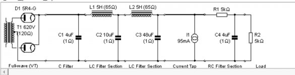
I've made a few changes to the power supply as shown below. Simplified it a bit, and decided to be a little more tolerant of ripple on the B+ to the SV-811. Oh, and I decided to go with tube rectification. I was thinking SS because my memory was that the power transformers lacked center taps on the plate voltage, but I was pleasantly surprised after I blew the dust off to find center taps! I guess that happens when a project has a 20 year delay.
Next question on power supply: If I'm going to smooth and filter the 6.3V for the SV-811, why wouldn't I extend that same supply to the 6EA7? What are the cons of having the driver tube and power tube filaments on the same supply?
Next question on power supply: If I'm going to smooth and filter the 6.3V for the SV-811, why wouldn't I extend that same supply to the 6EA7? What are the cons of having the driver tube and power tube filaments on the same supply?
Attachments
Last edited:
audiowize, that makes sense, although I have a strange faith in my Thorardson 6A filament transformers. They are vintage ham gear and somewhere I got the impression that they are significantly underrated.
But more to the point, I plan a delayed turn-on for B+ until after the SV811 filaments are warmed up. It would be easy to implement the same delay on the 6EA7 if its filaments were on the same filament transformer as the power tube, much harder if it's powered from a winding on the main transformer.
Is it desired or important to have the 6EA7 filaments turned on before B1+ hits it?
Full wave rectification in PSUD
I was surprised to see this statement in the help section on the transformer/rectifier: "For full wave rectifiers, use the voltage for one side only. For example, if the transformer off load voltage is 350-0-350V (700V end to end), the correct value to enter is 350."
Does that seem right? Isn't that for a half wave rectifier?
The help page is correct.
Most tube rectifiers are two diodes in one for use as a full wave rectifier.
Right now, TV damper diodes are popular, those tubes are single diodes so you’d need two for full wave rectification but they are tough tubes and cheap too!
The only downside to full wave rectification is that your transformer has to be larger in that you can only use one side at a time. With bridge rectifiers you need physically less iron.
Thanks, jdg123.
After I thought about it a bit, I had one of those light bulb moments. I understood this stuff better 20 years ago, but it is slowly coming back. I still don't know exactly how to model the loads, but I think I'm close enough on the design that I can breadboard it and see how it actually measures.
After I thought about it a bit, I had one of those light bulb moments. I understood this stuff better 20 years ago, but it is slowly coming back. I still don't know exactly how to model the loads, but I think I'm close enough on the design that I can breadboard it and see how it actually measures.

- Home
- Amplifiers
- Tubes / Valves
- SE SV-811-10 power supply