Hi Everybody,
I see that John Broskie's supertriode ideas pop up from time to time here. So I'd like to share my inspiration with you all. I like John's blog very much and get a lot of new knowledge from his posts.
To make a long story short, I have 24-32 Ohm headphones (Senn and Phill ones) and desire to make my dream set of tube sound line. The source is Chinese CS4398 DAC kit improved by John's BCF buffer-filter (instead of OpAmps) and CM6631A transport.
For my headphones I decided (for now) to create a hybrid amp using supertriode approach. It combines valve footprint with the power of MOSFETs.
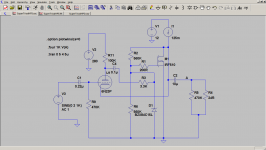
The theory is as follows: https://www.tubecad.com/2017/03/19/Super-Triode Concept, Cathode-Follower Buffer.png
I created a model in LTSPICE and it looks very promising.
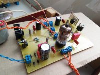
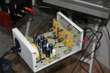
I made the first prototype with LM317 as current sources. Output electrolytes shunted by polypropylene. Also I put 200 Ohm resistor into the grid chain. Power source is unstable rectified 12VAC. The gate is protected with 18V zener. Heater AC 6V is lifted up by about 40V above ground. The valve is Soviet replica of 6DJ8 - 6N23P.
I do not have any measurements yet but the more I listen to it the more I love it. No any hum or noise. Bass is deep. I hear the scene.
The next step is to make current sources of descrete components - classic PMOS+PNP. Also I'd like to implement CS for valve instead of 100K resistor. Maybe also I will rectify heater to not hear 50 Hz hum at start and put relay with delay to avoid clicks.
I've got an advice to change potential on cathod down to have more voltage range. It can be done by decreasing of R2 value. It also makes the 2nd harmonic lower.
Any comments, ideas?
Thanks,
Vlad
I see that John Broskie's supertriode ideas pop up from time to time here. So I'd like to share my inspiration with you all. I like John's blog very much and get a lot of new knowledge from his posts.
To make a long story short, I have 24-32 Ohm headphones (Senn and Phill ones) and desire to make my dream set of tube sound line. The source is Chinese CS4398 DAC kit improved by John's BCF buffer-filter (instead of OpAmps) and CM6631A transport.
For my headphones I decided (for now) to create a hybrid amp using supertriode approach. It combines valve footprint with the power of MOSFETs.
The theory is as follows: https://www.tubecad.com/2017/03/19/Super-Triode Concept, Cathode-Follower Buffer.png
I created a model in LTSPICE and it looks very promising.
I made the first prototype with LM317 as current sources. Output electrolytes shunted by polypropylene. Also I put 200 Ohm resistor into the grid chain. Power source is unstable rectified 12VAC. The gate is protected with 18V zener. Heater AC 6V is lifted up by about 40V above ground. The valve is Soviet replica of 6DJ8 - 6N23P.
I do not have any measurements yet but the more I listen to it the more I love it. No any hum or noise. Bass is deep. I hear the scene.
The next step is to make current sources of descrete components - classic PMOS+PNP. Also I'd like to implement CS for valve instead of 100K resistor. Maybe also I will rectify heater to not hear 50 Hz hum at start and put relay with delay to avoid clicks.
I've got an advice to change potential on cathod down to have more voltage range. It can be done by decreasing of R2 value. It also makes the 2nd harmonic lower.
Any comments, ideas?
Thanks,
Vlad
Attachments

Last edited:
I'd love to try something similar with the subminiature 6N16B triode.
Good choice. I have phono stage made of 6N17B/6N16B tubes.
Attachments
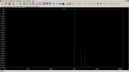
With all the same conditions, 6N16B and 32 Ohm load simulation shows nice results:
Harmonic Frequency Fourier Normalized Phase Normalized
Number [Hz] Component Component [degree] Phase [deg]
1 1.000e+03 1.697e+00 1.000e+00 26.41° 0.00°
2 2.000e+03 2.025e-04 1.193e-04 159.44° 133.03°
3 3.000e+03 6.006e-05 3.539e-05 96.55° 70.14°
4 4.000e+03 3.582e-06 2.111e-06 79.11° 52.70°
5 5.000e+03 1.017e-06 5.993e-07 -14.24° -40.65°
6 6.000e+03 1.123e-06 6.620e-07 81.54° 55.14°
7 7.000e+03 1.253e-06 7.381e-07 93.22° 66.81°
8 8.000e+03 1.166e-06 6.871e-07 93.00° 66.59°
9 9.000e+03 1.103e-06 6.502e-07 92.34° 65.93°
Total Harmonic Distortion: 0.012448%(0.010775%)
Attachments
- Status
- This old topic is closed. If you want to reopen this topic, contact a moderator using the "Report Post" button.