I thought I’d share some simulation and experimental results for a PP supertriode amp using ECL85/6GV8. I believe the supertriode connection was developed by the Japanese and has popped up from time to time on diyAudio. John Broskie has explored the concept at length:
SuperTriode
Single-Ended Amplifiers & Super-Triodes
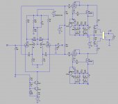
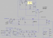
My aim (bearing in mind that I’m doing this for fun / intellectual challenge and not in pursuit of some sort of audio nirvana) was to use a pair of triodes and high voltage mosfets in supertriode connection in a fairly conventional push-pull arrangement with a mains toroidal used as an output transformer. Schematic for amp and power supply below. This was for proof of concept, and is supplied with a balanced signal (I used a cheap DRV134 board). +/- 1.5Vrms for 50W into 8 ohms at around 0.1% THD (sim) with 12 dB gNFB.
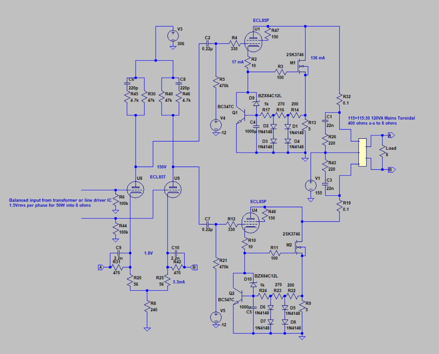

Comments on the schematic:
• Stability networks actual values after squarewave testing. Zobels on Output Tx primary gave a slightly cleaner squarewave on 4 ohm loads but probably not necessary
• Diodes D1-D4 and D5-D8 allow class AB operation of bias servos.
• 12V zeners D9/D10 stop mosfets from potentially destroying themselves while C4/C5 charge at start-up (I blew one when I turned on B+ with valves warm and a longer RC time constant)
• ECL85 output bias voltage (-12V in schematic) adjusted to give balanced total current through each half of transformer. In practice not too sensitive and very stable.
• Mosfets dissipating about 21W at 136 mA , set by 5 ohm resistor. 25W/170mA would be a bit lower distortion.
• Power from 115V stepdown or isolation transformer (cheap!) with doubling to provide B+ to drivers. Circuit from the best voltage doubler -the 4X8!
I’m using a cheap 120VA 115+115:30V (32.5V unloaded) toroidal as a 400:8 transformer, which is theoretically good for 112W into 8 ohms @50Hz, and allows decent power at lower frequencies.
ECL85 used because I had some, the pentode section looks very good triode strapped (see SPICE Design of 6F5P SET Amplifier and attachment), and it was easy to get the voltages right for the mosfet drive. 2SK3746 is a 1500V mosfet, chosen because I can keep within the DC SOA and bias current doesn’t move around with temperature (at least according to datasheet). Scope pictures to follow.
SuperTriode
Single-Ended Amplifiers & Super-Triodes
My aim (bearing in mind that I’m doing this for fun / intellectual challenge and not in pursuit of some sort of audio nirvana) was to use a pair of triodes and high voltage mosfets in supertriode connection in a fairly conventional push-pull arrangement with a mains toroidal used as an output transformer. Schematic for amp and power supply below. This was for proof of concept, and is supplied with a balanced signal (I used a cheap DRV134 board). +/- 1.5Vrms for 50W into 8 ohms at around 0.1% THD (sim) with 12 dB gNFB.
Comments on the schematic:
• Stability networks actual values after squarewave testing. Zobels on Output Tx primary gave a slightly cleaner squarewave on 4 ohm loads but probably not necessary
• Diodes D1-D4 and D5-D8 allow class AB operation of bias servos.
• 12V zeners D9/D10 stop mosfets from potentially destroying themselves while C4/C5 charge at start-up (I blew one when I turned on B+ with valves warm and a longer RC time constant)
• ECL85 output bias voltage (-12V in schematic) adjusted to give balanced total current through each half of transformer. In practice not too sensitive and very stable.
• Mosfets dissipating about 21W at 136 mA , set by 5 ohm resistor. 25W/170mA would be a bit lower distortion.
• Power from 115V stepdown or isolation transformer (cheap!) with doubling to provide B+ to drivers. Circuit from the best voltage doubler -the 4X8!
I’m using a cheap 120VA 115+115:30V (32.5V unloaded) toroidal as a 400:8 transformer, which is theoretically good for 112W into 8 ohms @50Hz, and allows decent power at lower frequencies.
ECL85 used because I had some, the pentode section looks very good triode strapped (see SPICE Design of 6F5P SET Amplifier and attachment), and it was easy to get the voltages right for the mosfet drive. 2SK3746 is a 1500V mosfet, chosen because I can keep within the DC SOA and bias current doesn’t move around with temperature (at least according to datasheet). Scope pictures to follow.
Attachments
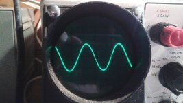
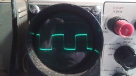
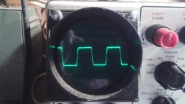
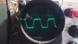
Power at clipping about 70 watts into 8 ohms (sorry no picture, my test load can’t take this for more than a few seconds). -3dB about 50 kHz open loop with no compensation. After compensation and 12 dB feedback, -3dB at 55 kHz (could push this higher if I was less fussy about squarewave response). I need to get a decent test load but at 30 Hz I was approaching 50 watts before visible waveform distortion. Signal generator and oscilloscope both from 1960’s, 1kHz photo is identical to what was present at generator output.
Next a schematic for a folded cascade phase splitter that looks promising in the simulator.
Next a schematic for a folded cascade phase splitter that looks promising in the simulator.
Attachments
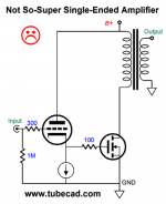
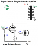
Super triode?
It is a triode-pentode with the screen grid connected to the anode of the pentode for lower gain in triode mode as a standard cathode follower driving a pair of FETs
No such thing as a "Super Triode".
It would be a standard cathode follower had the pentode's anode connect to HV+ instead of the OPT.
I did the same with bipolar NPN as opposed to mosfet. The sound is wonderful probably better then a power tube amp as the 6922 is more linear then a power tube.
12AX7 gain stage > 2N5551 splitter > 6922 + MJE13004 = 30w RMS from 150v B+ 4K transformer.
no plate feedback in fig.1 = awful sound quality and huge gain. Transistors do not have collector feedback like tubes
what is your idle current ?
12AX7 gain stage > 2N5551 splitter > 6922 + MJE13004 = 30w RMS from 150v B+ 4K transformer.
no plate feedback in fig.1 = awful sound quality and huge gain. Transistors do not have collector feedback like tubes
what is your idle current ?
Last edited:
what is your idle current ?
I was aiming for about 170mA (simulation shows this as the sweet spot) but got about 135mA as the actual beta and Vbe for the bias servo transistor was a little different to the simulation. I will reduce the value of the 5 ohm source resistor to increase the bias current. I want to keep the mosfet dissipation to about 25 watts per device to avoid massive heatsinks.
I biased the BJT with a 1N4148 to prevent turn off and set bias to 80ma with the emitter resistor and 6922 cutoff voltage.
Are you able to post a schematic or sketch of your design?
Thanks, I do actually remember seeing that at the time. A lot of interesting stuff flies under the radar on this forum ")
What power do you get out of it? With mine the anode voltage can be pulled down to about 40V minimum giving power of (155-40)^2*2/400 = 66W. Yours maybe 15-20W with 200V B+ and 3500 ohm primary, probably more of it would be in class A.
What power do you get out of it? With mine the anode voltage can be pulled down to about 40V minimum giving power of (155-40)^2*2/400 = 66W. Yours maybe 15-20W with 200V B+ and 3500 ohm primary, probably more of it would be in class A.
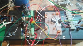
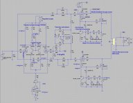
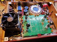
Some follow-up on this. I’ve 80% completed an amplifier based on this topology, picture and schematic attached. I ended up going with the folded cascode LTP phase splitter which has worked very well. Other changes from previous schematic posted are:
• Eliminated the higher voltage supply for the phase splitter/driver. Works fine supplied with a regulated 139 V derived from the main B+ of ~160V.
• Used cascoded jfets for the LTP CCS with trimmer for current adjustment. This lets me set the voltage on the 22k cascode load resistors R8/R18 at about half the triode anode voltage.
• Some refinement to the mosfet bias servo to ensure stable bias across the full operating range. Was originally set up so bias increased a bit as output transitioned into class B, which gave good distortion figures on steady state sine waves but resulted in damped low frequency oscillation (~3 Hz) after loud music transients.
• Added a step network C3+R41 / C14+R44 as belt and braces for LF stability
• Mosfet feedback through screen rather than anode, from a suggestion by Indra1. Removes the valve current (which is constant and not contributing to power output) from the output transformer, also increases power by allowing greater voltage swing before grid current starts. Otherwise gives very similar performance to a triode connection
• Increased mosfet bias to 200mA for ~30W dissipation.
• Reduced global feedback a little. Now about 10 dB to get full output power of ~60W into 8 ohms from 1V rms input.
The amp has very low noise and hum, I can’t hear anything at all with my ear at the speaker cone with no signal. Output impedance is about 3 ohms without feedback and 0.8 ohms with feedback.
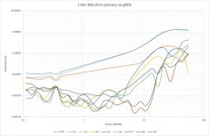
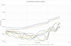
I’ve bought a decent soundcard and have used REW to do some distortion testing. Distortion results change significantly when valves are swapped, demonstrating that distortion profile results mostly from the valve rather than the mosfet. Distortion is significantly lower with a 12 ohm load (600 ohms primary) compared to an 8 ohm load (400 ohms primary) but with lower maximum power available.
THD summary for the best pair tested:
8 ohm load with 10 dB gNFB
1 watt 0.01%
10 watts 0.10%
30 watts 0.46%
50 watts 0.50%
8 ohm load with no gNFB
1 watt 0.026%
10 watts 0.25%
30 watts 1.27%
50 watts 1.27%
12 ohm load with 10 dB gNFB
1 watt 0.004%
10 watts 0.014%
30 watts 0.08%
40 watts 0.19%
12 ohm load with no NFB
1 watt 0.010%
10 watts 0.07%
30 watts 0.23%
40 watts 0.41%
More detailed charts from REW in the next post.
• Eliminated the higher voltage supply for the phase splitter/driver. Works fine supplied with a regulated 139 V derived from the main B+ of ~160V.
• Used cascoded jfets for the LTP CCS with trimmer for current adjustment. This lets me set the voltage on the 22k cascode load resistors R8/R18 at about half the triode anode voltage.
• Some refinement to the mosfet bias servo to ensure stable bias across the full operating range. Was originally set up so bias increased a bit as output transitioned into class B, which gave good distortion figures on steady state sine waves but resulted in damped low frequency oscillation (~3 Hz) after loud music transients.
• Added a step network C3+R41 / C14+R44 as belt and braces for LF stability
• Mosfet feedback through screen rather than anode, from a suggestion by Indra1. Removes the valve current (which is constant and not contributing to power output) from the output transformer, also increases power by allowing greater voltage swing before grid current starts. Otherwise gives very similar performance to a triode connection
• Increased mosfet bias to 200mA for ~30W dissipation.
• Reduced global feedback a little. Now about 10 dB to get full output power of ~60W into 8 ohms from 1V rms input.
The amp has very low noise and hum, I can’t hear anything at all with my ear at the speaker cone with no signal. Output impedance is about 3 ohms without feedback and 0.8 ohms with feedback.
I’ve bought a decent soundcard and have used REW to do some distortion testing. Distortion results change significantly when valves are swapped, demonstrating that distortion profile results mostly from the valve rather than the mosfet. Distortion is significantly lower with a 12 ohm load (600 ohms primary) compared to an 8 ohm load (400 ohms primary) but with lower maximum power available.
THD summary for the best pair tested:
8 ohm load with 10 dB gNFB
1 watt 0.01%
10 watts 0.10%
30 watts 0.46%
50 watts 0.50%
8 ohm load with no gNFB
1 watt 0.026%
10 watts 0.25%
30 watts 1.27%
50 watts 1.27%
12 ohm load with 10 dB gNFB
1 watt 0.004%
10 watts 0.014%
30 watts 0.08%
40 watts 0.19%
12 ohm load with no NFB
1 watt 0.010%
10 watts 0.07%
30 watts 0.23%
40 watts 0.41%
More detailed charts from REW in the next post.
Attachments
- Status
- This old topic is closed. If you want to reopen this topic, contact a moderator using the "Report Post" button.
- Home
- Amplifiers
- Tubes / Valves
- ECL85/6GV8 PP Supertriode