Apologies for going further off topic, but would a tube like this run on a 'standard' 6.3V heater supply?PRR is right. The tubes are independent. So long as your 16 VAC supply can handle 600 ma (0.6 amp), you're in business. In fact it scales: use as many channels as you like. 'n' say. Current supply for heaters is n × 300 ma.
GoatGuy
I've a handful of UCL83's (rated at 100mA) I've been looking for a use for, but have always been confused by their being rated by current instead of voltage.
I think I understand now why the datasheet lists the current as opposed to a specific voltage. Vhk max for a Mullard UCL83 is listed as 100V, but how low can we go?
Matt.
Last edited:
Not sure what's to get confused about - the datasheets always specify both voltage and current... UCL83 @ The Valve Museum
In this case 38 volts, 100mA. In other words it will drop 38 volts when you pass 100mA through the heater - and in more other words, the supply for the heater needs to be 38 volts for a single tube, or greater if this heater is in series with others.
In this case 38 volts, 100mA. In other words it will drop 38 volts when you pass 100mA through the heater - and in more other words, the supply for the heater needs to be 38 volts for a single tube, or greater if this heater is in series with others.
Thanks.
As usual, I should have paid closer attention to the datasheet!
The description reads '...100mA heater intended for use... ' etc. I hadn't noticed a couple of lines further down (yes, just under the big, uppercase letters spelling out HEATER") ), it does indeed specify a 38V supply.
), it does indeed specify a 38V supply.
Matt.
As usual, I should have paid closer attention to the datasheet!
The description reads '...100mA heater intended for use... ' etc. I hadn't noticed a couple of lines further down (yes, just under the big, uppercase letters spelling out HEATER
), it does indeed specify a 38V supply. Matt.
Interesting.. Would that need a coupling cap followed by a R//C combination?You could add the option for plate-to-cathode feedback in case you want to play with that? (i.e. ring of two)
And I guess this would connect directly to the input cathode, rather than the middle of the split R_k?
I can maybe use my R3 in double duty if I make a footprint with 3 pads to give the choice. It's tight spacing though...
Yes.Interesting.. Would that need a coupling cap followed by a R//C combination?
Whichever you like really.And I guess this would connect directly to the input cathode, rather than the middle of the split R_k?
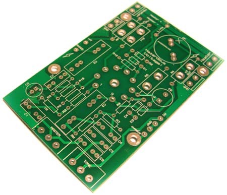
Thought I'd mention here that I've got some general purpose ECL86 PCBs available. I made then as part of my universal PCB range but I don't think I'll make them permanent, so if anyone wants one while stocks last, now's your chance.
The Valve Wizard
The Valve Wizard
Build update
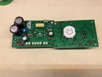
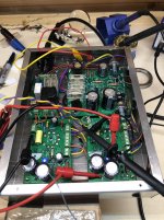
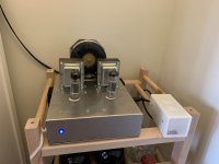
Over the last couple of weeks I've finally got this build together and making sound.
Photos below.
Just have to tune the GNFB and finalize the signal inputs (had thought to hard-wire a RaspberryPi / DAC and use it as a streaming device).
Playing through my 8ohm living room Wharfedales (so a slight mismatch) it sounds good. Not much bass compared to my DCPP (hoping the GNFB might improve that a bit) but perfectly respectable to my ears.
I'll post some scope traces etc when I get the time. Also, if anyone wants one of my spare PCBs let me know.
Attachments
Last edited:
A comment to "LeftHandFool" regarding 100mA filament : Back in the dark -50 price pressure on homedevices resultet in a flood of devices that lacked mains transformer. B+ was made by rectifying AC, and the filaments was connected in series. Thats why tubes were made that used same current( but different voltages). European 'U' series all used 100mA current and was used for radio and record players of the cheap type. Similar tubes was adapter for television sets namely the 'P' series that used 300mA / tube
'U' and 'P' was the first letter of the tube designation, the 6.3V was named 'E'.
The remaining tube designation represented tubes with same properties, UCL82 PCL82 and ECL82 all has same properties, only filament was different. A few tubes ( EL84 and PL84 violated this ) This might be a rescue for amps using exotic tubes ( heath AA-32 for instance using ECL86, which might be replaced by PCL86 and a modified filement power)
See Mullard–Philips tube designation - Wikipedia for further info.
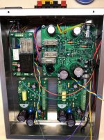
"Finished" and measurements
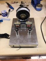
So after months of tinkering & tweaking I'm finished the physical build.
The last major change completed yesterday was replacing the tiny, vintage OTs with a set of new, beefier ones from VVT.
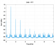
Result: what I consider a good sounding set-up for my kitchen. Puts out about 1W on the edge of clipping. Listening through my home-made miniKarlsonators there is a _slight_ lack of bass, but that could be the speakers and their position. A small bit of EQ solves that and makes for enjoyable listening, especially with jazz / piano stuff. Not so great with heavy rock.
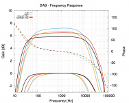
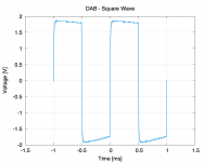
Attached are some readings taken:
- freq sweeps with old and new OTs, showing magnitude and relative to 1kHz level
- square wave response at 2Vpp 1kHz input
- FFT of 2Vpp 1kHz sine input
Slight mismatch between channels for some reason... Perhaps a coupling cap?
I've plenty of PCBs left over if anyone wants them to try this themselves.
So after months of tinkering & tweaking I'm finished the physical build.
The last major change completed yesterday was replacing the tiny, vintage OTs with a set of new, beefier ones from VVT.
Result: what I consider a good sounding set-up for my kitchen. Puts out about 1W on the edge of clipping. Listening through my home-made miniKarlsonators there is a _slight_ lack of bass, but that could be the speakers and their position. A small bit of EQ solves that and makes for enjoyable listening, especially with jazz / piano stuff. Not so great with heavy rock.
Attached are some readings taken:
- freq sweeps with old and new OTs, showing magnitude and relative to 1kHz level
- square wave response at 2Vpp 1kHz input
- FFT of 2Vpp 1kHz sine input
Slight mismatch between channels for some reason... Perhaps a coupling cap?
I've plenty of PCBs left over if anyone wants them to try this themselves.
Attachments
Last edited:
Should anyone wish to try building a PCL82/ECL82 system I've placed all the source files (KiCad) and gerbers needed at the following links.
SE-PCL boards: amps/HiFi-SE-PCL82 at master * tristancollins/amps * GitHub
Maida Regulator: amps/HiFi-MaidaRegulator at master * tristancollins/amps * GitHub
FET breakout boards:
amps/General-MOSFET-Breakout at master * tristancollins/amps * GitHub
amps/General-TO220-Breakout at master * tristancollins/amps * GitHub
5V supply and mains relay: amps/HiFi-5V-Supply-Relay at master * tristancollins/amps * GitHub
- Status
- This old topic is closed. If you want to reopen this topic, contact a moderator using the "Report Post" button.
- Home
- Amplifiers
- Tubes / Valves
- PCL82/ECL82 SE PCB design - thoughts?