I believe this is another uC bias controller:
Volt Amp Co - Guitar Amp Builder - Aston Electronics - Recording Notes
I think this is the patent:
GB2462368A - Adjustment of quiescent cathode current in a thermionic valve audio amplifier
- Google Patents
"KBO had support from a number of North East backers. It won £90,000 from NorthStar Equity Investors’ Proof of Concept fund, developed its prototype with help from Business Link and got £20,000 from the North East England Investment Centre. The process was then advanced by a grant of £20,000 from One North East. In all, Andy estimates the product has taken 18 months and around £200,000 to develop."
Lol, so that's £1000 for a hobby project and £199000 of public money for being shrewd!
Last edited:
Dunno. It just seems like using a sledge-hammer to adjust an eyeglass screw.
To me.
A computer scientist.
IF the goal is push-pull output finals current balance perfection, it is answered easily enough with analogue-domain servos.
IF the goal is a particular specific quiescent operating current … again, its easily handled with analogue (near) constant-current source designs.
(these are not mutually exclusive either)
IF however, the goal is rapid adaptive settling followed by very slow moving 'locked' (and probably also finely balanced) quiescent current, OR IF some of the “self-evaluation-and-sophisticated-startup-and-shutdown” behavior is desired… well, its much harder in the analogue domain, and rather trivial in the digital.
BUT as noted above, I worry strongly about the introduction of a little RF noise transmitter inside one's otherwise fastidiously designed, grounded, shielded and electromagnetically quiet amplifier. Seriously. Microprocessors are noisy. ALL of them.
To be fair, the 'spec' could also include a thick copper perforated Faraday cage around the microprocessor and its I/O pins could all be protected from leaking RF with mid-μH ferrite looped cores. It could. If so, then I'd worry much less bout the ancillary RF.
GoatGuy
Dunno. It just seems like using a sledge-hammer to adjust an eyeglass screw.
To me.
A computer scientist.
GoatGuy
As someone who has used microcontrollers for 30+ years knocking up a PIC circuit is easy. I have same amount of time coding so have loads of code I can draw on already written for A2D, I2C etc etc
It can be a bit daunting for someone new to microcontroller circuits and coding.
The first one is the hardest then they get easier.
With 8 pin PIC's for peanuts its never been a better time to get into them.
I have done irs2092 reset circuit using a2d off VCC.
I have done speaker protect circuit just using PIC I/o pins to detect DC on AC signal.
I have done cold start circuit using PIC and triac to ramp up mains slowly.
I have done power measuring circuit using a PIC.
And many more....
With the onset of Arduino etc people can have fun with amplifiers circuits.
Last edited:
I am surprised that you can get a UK patent for something so obvious. Has the Patent Office function been contracted out to a US company? I am less surprised that you can get funding for something so obvious.
Interesting it only adjusts bias in quiet periods.
A DC servo works all the time.
The microcontroller could using an A2D to integrate the waveform and use result to set bias current.
I used a similar technique in an amplifier power measuring system using a microcontroller.
I have been working for some time on a sort of RTOS for valve amplifiers based on a 18F4550 (or similar) PIC ucontroller. See docs attached.
To me this development was kind of obvious, maybe I should have crowd-funded it!
To me this development was kind of obvious, maybe I should have crowd-funded it!
Attachments
The PIC18f4550 is a great processor.
I have used it for all sorts of USB projects.
If you want to link it to a PC via USB then there is a great project at Waiting for Friday – Weekend electronics engineering
It has the PIC C code and PC C# code in a working form.
I just take their code and alter it for my own uses.
Its just a matter of digging into the PIC code to get into the comms interface and same on the PC.
I have done a USB audio mixer, USB LC meter and USB oscilloscope.
It is indeed an excellent solution for many embedded projects. No tiny SMD pins to solder, still a very compact footprint, enough RAM and ROM for complex applications, and... cheap! At some point I considered using a RPI but it didn't even come close in terms of performance and cost.
I will dig the example you mentioned. Thanks!
I will dig the example you mentioned. Thanks!
I made up these little boards using a PIC16F1825. It does not adjust the bias but monitors up to 4 tubes and tells you if any tube is 5% out of balance and shuts down the amp with a 10% imbalance. So for push-pull it compares the pair of tubes constantly looking for imbalance.
The main idea here being to shut down the amp if a tube starts to run away
The 16F1825 has a 1.024V internal reference for the A/D converter so you just need like a 6 ohm cathode resistor to use to measure the tube current. At $2.00 each these little things can really do a lot.
The main idea here being to shut down the amp if a tube starts to run away
The 16F1825 has a 1.024V internal reference for the A/D converter so you just need like a 6 ohm cathode resistor to use to measure the tube current. At $2.00 each these little things can really do a lot.
Attachments
It's not a problem when you have an internal clock and the IO pins aren't actually doing anything at high speed (and not really a problem with an external clock either since they run at Mhz). We use uCs all the time in mic amps full of transformers and 80dB of gain.Seriously. Microprocessors are noisy. ALL of them.
It's not a problem when you have an internal clock and the IO pins aren't actually doing anything at high speed (and not really a problem with an external clock either since they run at Mhz). We use uCs all the time in mic amps full of transformers and 80dB of gain.
Yes, microcontrollers can sit comfortably with most audio components, though some opamps may need to be checked for rectification (demodulation) of out-of-band signals. Recent opamp designs claim to have taken steps to improve EMI immunity.
TI have a note on the effects of EMI rectification, and susceptibility generally:
http://www.ti.com/lit/an/sboa128a/sboa128a.pdf
Well-designed microcontroller modules minimise risk in a few ways. Avoidance of having IO pins toggling (as Merlin mentions) is among the most important, and in the case of a bias controller, avoid using a PWM output to control an analogue value - PWMs will emit HF to VHF and also audio or ultrasonic noise, depending on the PWM's period.
Choosing a low-power Micon is effective, since the elemental capacitances are lower in chips with advanced CMOS processes, which means that the switching currents are small, and low-emission. This is better still in versions aimed at battery power - even 32 bit ARM Cortex-M types - some of these can operate with a 3.3V supply, and run the core at a programmable internally regulated low voltage, down to (example) 1.5V. Boards with these on can get through EN5022 without an enclosure, if the board design is up to snuff.
In the Handheld computing phase of my design life, I designed a Handheld PC processor board which had to live with a 900/1800MHz data radio in the same small enclosure. The processor board with its 32-bit MIPS processor, and 32-bit synchronous DRAM and 32-bit external graphics controller IC made quite a mess over the EN55022 (CISPR 22) EMI plots in its first version. But with screening, filtering, and most importantly careful PCB design, this was diminished to the point where the data-radio's receiver was not de-sensed to any meaningful extent.
I mention all this because I would find it easier to repeat the exercise of controlling the EMI from processors, than try to fit the a susceptible audio module right next to a 400V rms transformer feeding a rectifier and 220µF capacitor, yet I sense that many folks are more worried about the Micon, and ignore the effects of the rectifier!
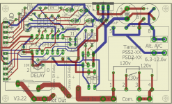
Hello. This My Microcontroller Bias supply system.
Features of my device
• Setup cathode current and cathode resistors using a computer application
• Connnecting to PC via USB
• Visualisation of cathode current changes in real time in application
• Full digital control with ARM Cortex M0 48MHz
• 4 ADC with 12-bit precision for measuring cathode current for each tube
• 4 DAC with 16-bit precision for each tube
• Regulation of cathode current of the tubes from 1mA to 200mA
• Setup any nominal cathode resistors from 1.0 Ohm to 10.0 Ohm with the step 0.1 Ohm for each tube
• Noise reduction from 9-Pole Low-Pass filter output voltage for each tube , resulting clearer high-frequency tones
• Slow ramp up of current over a further 60 s – 200 s
• Changeable turn on delay time from 1 to 300 second
An externally hosted image should be here but it was not working when we last tested it.
An externally hosted image should be here but it was not working when we last tested it.
An externally hosted image should be here but it was not working when we last tested it.
An externally hosted image should be here but it was not working when we last tested it.
An externally hosted image should be here but it was not working when we last tested it.
An externally hosted image should be here but it was not working when we last tested it.
Adjusting bias in quiet periods is not new. I remember seeing an analogue system for doing this discussed on this forum a few years ago.
I did that on a breadbord long time ago using S/H and found that it not worth it, especially when playing classical music where pauses are rare. Digital approach could be better, no discharging capacitor. Still, what's the point in adjustments during each several minutes that are needed probably once an year?
Last edited:
Don't know if its still on his 'site but George (Tubelab) did a very high tech project at one stage with lots of highly offensive silicon and binary code to control its various functions including bias iirc
The dsPIC powered amplifier was an entry into a design contest sponsored by Circuit Cellar Magazine and Microchip to gain attention for their newly introduced dsPIC chips. The contest was announced in late 2006 and ran for most of 2007. I used the dsPIC chip to monitor output tube current, driver tube current and control the bias, among lots of other duties. The output stage was a cathode follower because I needed it's high PSRR for the real unique feature of the amplifier.
I was a cell phone / two way radio designer at the time and I leveraged a new technique called (power) supply modulation to gain a large improvement in (RF) power amplifier efficiency. Since tube dissipation is usually the limiting factor in a single ended class A amplifier, an improvement in output stage efficiency directly translates to a boost in power output for the same tube dissipation. How much improvement? 30 watts from a single 6AS7 with both triodes in parallel compared to less than 10 watts without the "magic."
The dsPIC chosen for the design had rudimentary SMPS feastures built into it, along with some 1 MSPS converters to sample the audio so I used this to design the modulated buck converter for the plate supply. Other features like tube testing and matching, parameter memory and tube health checks were mentioned in the article, but the code was never written. I built this thing in 2007, and submitted it do the design contest where it won the prize for "best use of SMPS features" category. This resulted in me writing an article for the magazine in 2008, which was published in 2009. It is included here. Sadly there hasn't been much interest in any of this, so I never revisited it, but I may get back to it someday.
I am surprised that you can get a UK patent for something so obvious.
The schematics and much of the documentation was posted on my web site some time before the Circuit Cellar magazine article was published in 2009. The contest winners, projects and abstracts were published in the magazine, and on Circuit Cellars web site in 2007, and the concept of microprocessor bias control had been around for some time, in magazine articles and web sites before that. It should be impossible to patent something that was published previously, or "obvious to those skilled in the art."
In the Handheld computing phase of my design life, I designed a Handheld PC processor board which had to live with a 900/1800MHz data radio in the same small enclosure.
I was a design engineer at Motorola for 41 years. We put the first microprocessor in a hand held "walkie talkie" two way radio in 1978. It took a few years to learn all there was to know about getting this right, but keeping the microprocessor out of low level microphone audio was far easier than keeping the 5 watt VHF transmitter in the walkie talkie from driving the processor nuts with its antenna 2 inches away. By the early 90's we were stuffing DSP's into radios and cell phones. Again the pulsing transmitter (TDMA) of an iDEN or GSM phone is a far larger noise problem than the micro or DSP.
Attachments
- Status
- This old topic is closed. If you want to reopen this topic, contact a moderator using the "Report Post" button.
- Home
- Amplifiers
- Tubes / Valves
- microcontroller for bias?