While I wait for my order from Edcor, I decided to use up some extra crap and build a preamp. 
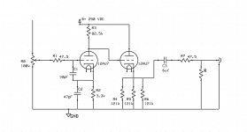
A while back I had a chance to listen to a Conrad-Johnson PV10a with a similar setup to mine, and I've decided to use its design as a starting point. That said, my B+ is likely different, so I know there may be some changes that have to be made, and the values on the PV10 schematic are very hard to read. I'd be very grateful if someone with more experience than me could look over this and point out any mistakes. I did change the output capacitor value from 4 uF to 6 uF based on what I have on hand.
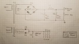
There are a few changes I need to make to the power supply design, including a bridge rectifier rated for high voltage use and putting in a regulator on the filament supply, but it'd be nice to get a second opinion from you all.
Thanks guys, this forum has been a big help.
A while back I had a chance to listen to a Conrad-Johnson PV10a with a similar setup to mine, and I've decided to use its design as a starting point. That said, my B+ is likely different, so I know there may be some changes that have to be made, and the values on the PV10 schematic are very hard to read. I'd be very grateful if someone with more experience than me could look over this and point out any mistakes. I did change the output capacitor value from 4 uF to 6 uF based on what I have on hand.
There are a few changes I need to make to the power supply design, including a bridge rectifier rated for high voltage use and putting in a regulator on the filament supply, but it'd be nice to get a second opinion from you all.
Thanks guys, this forum has been a big help.
Attachments
Last edited:
That was part of the PV10 schematic that I wasn't able to read (very fuzzy image). Would a 12AT7 make more sense in this design? I would think a 12AX7 would have too much gain for this.
The 'U7 is a "bean counter" favorite. If the doubled heater draw is not a problem, a 6CG7/6FQ7 or 12BH7 usually works, without parts value changes, well.
Yeah, this is like the Bottlehead Foreplay from the 90's (long ago discontinued, for good reasons).
You don't need DC on the heaters, but it doesn't hurt anything.
The 10pF and 47pF caps aren't really doing anything, just leave them out.
R7 serves no useful purpose.
R3 can be the same value as the paralleled value of R4/5/6. Maybe draw a load line for something like 39K and see how it looks.
The 12AU7 is indeed a bit of a weak point. The 6CG7 and 5687 are good substitutes. The 12AT7 and 6922 are not.
This preamp circuit has too much gain for just about everybody. A -20dB pad built into the input/attenuator will make it much more useful. This could be accomplished by changing the pot to 10K and adding a 100K resistor between the input of the pot and output of your selector switch.
On the heater circuit, consider not earthing the negative end, but rather bias it up to 50V or so.
PV9a
The Conrad Johnson PV9a uses the 6FQ7 and 5751 in a similar arrangement. I own both a PV10 and PV9a and can say the PV9a is the better of the two.
I wouldn't say either of them are that neutral sounding and probably have that 'Tube Sound' that some people like. Yes a bit coloured.
The Conrad Johnson PV9a uses the 6FQ7 and 5751 in a similar arrangement. I own both a PV10 and PV9a and can say the PV9a is the better of the two.
I wouldn't say either of them are that neutral sounding and probably have that 'Tube Sound' that some people like. Yes a bit coloured.
Also worth notin gis that Frank has posted (probably a whole thread) a 6SN7 variation of this circuit.
dave
Is there a significant difference between the 6SN7 and the 6CG7 besides the SN7 using an Octal socket? I'm not too worried about heater current. I'm okay with some design changes- this is just my starting point. Also, isn't the 6SN7 happier at 280-300V rather than the 250V B+ I'm using?
Thanks for the suggestions by the way.
Any other design changes worth making? Alternatively, if there is a "Go to" line stage preamp design, I'm not opposed to making a change. I was planning to buy tubes for this anyways, so it's no big deal to change that. I already have the power transformer though, so I'd prefer not to change that.
I built a PV10 clone about 15 years ago and I am still enjoying it. Was a great learning experience and ended up with a nice sounding pre. I added an additional power supply board similar to what this guy, https://esperienzehifi.wordpress.com/2016/10/09/esperienza-di-clonazione/amp/ has done, effectively turning it into a PV12 clone.
- Status
- This old topic is closed. If you want to reopen this topic, contact a moderator using the "Report Post" button.
- Home
- Amplifiers
- Tubes / Valves
- PV10 Clone Schematic