Hello,
I am restoring my old Radford STA-25 series 3 amplifier. The amplifier was a flea market find and the cosmetic condition was really bad. The traces over the PCBs were pealing off and almost all caps were out of spec. I have ordered new boards from Radford UK and cleaned the amp. When I have placed the new boards in and wired them, I have seen oscillation in the input stage that I haven’t seen before.
My test setup is as follows:
- the output impedance selector is at 8ohm position
- shorted rca sockets are placed in both inputs
- 8ohm dummy resistors are connected at both outputs
- a two channel oscilloscope is monitoring both outputs from the dummy resistor leads
As the amplifier warms up, the oscillation starts. When I unplug both EF86s, there is no oscillation. Similarly, when I plug in one of them, to either channel, there is no oscillation either. When I connect the EF86s and switch the output impedance selector to 4ohm position, the oscillation stops, however, the output is distorted.
I don’t know where to start, Can anybody give me a direction? I also don’t know what material I should share for the people who are willing to help, however the schematic of this STA-25 Series 3 is available online.
Best Wishes,
Dirk
Last edited:
Sorry, my mistake, I was trying to refer to the input stage gain pentode tubes, the EF86.
I'd would suspect the switch for selecting output impedance first, then feedback components and lastly output transformer wiring. I have a battered sta15 and have hard wired the transformer to the output ( 4 ohm ).Good luck hunting the issue.
Hi Dick,
What happens if you remove the feedback loop? (Junction of R2/3 and C4 or at the switch.).
Hello Alan,
I have left the feedback loop out, by disconnecting it from the switch. The oscillation is gone. Is this a good or a bad sign?
Best,
Dirk
I'd would suspect the switch for selecting output impedance first, then feedback components and lastly output transformer wiring. I have a battered sta15 and have hard wired the transformer to the output ( 4 ohm ).Good luck hunting the issue.
Hello Jonny,
I have also read it somwhere else that, these switches are handling more functions than they should. Apparently, the feedback is switching with the impedance selection and if there is something iffy with the switch, the outcome can ruin the signal.
Best,
Dirk
If removing the feedback loop stops the oscillation (good) there could be something wrong with the switch or its wiring. Check them carefully.
If they all check out OK, most likely you have the output transformer / pentode connections reversed. Try swapping 1 to 5 and 2 to 4 on the output transformers. Normal warning applies - Use a dummy load or low value speakers when testing!
Good luck.
If they all check out OK, most likely you have the output transformer / pentode connections reversed. Try swapping 1 to 5 and 2 to 4 on the output transformers. Normal warning applies - Use a dummy load or low value speakers when testing!
Good luck.
Yes, they are both marked as Radford Revival, M3173/WE and M3174WE.
Sorry been a busy day. Those are the right ones (they also did a version a different input tube which is why I wanted to ask).
Given the age I don't trust the impedance selector and even 30 years ago when I got mine that was the first thing I bypassed. As you noted as well as switching the output taps it switches in a different feedback network. That switch is now 50 years old!
I would bypass that and check the wiring carefully. Post pictures and we can double check for you.
We should have a 'most battered Radford' competition. Here is my entry
")
Attachments
I would bypass that and check the wiring carefully. Post pictures and we can double check for you.
We should have a 'most battered Radford' competition. Here is my entry
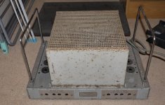
I literally found this in a thick, black plastic bag. The shiny chrome handles were sticking out, which triggered me to look inside. First, I saw the mains transformer, and I have thought to myself that it is an expensive component, if it is cheap, I should not pass it. After that, I saw two identical transformers, which made a click sound in my mind that this could be a tube amplifier "puzzle". Paid less than lunch money took it home, to my surprise, it was just missing the cage, the voltage selector and the impedance selector knobs.

This is the picture before I started the restoration. I haven't changed anything and brought it together as I have found it. To my surprise, it started working without any glitch. I still think to this day why the previous owner took it apart and buried in a plastic bag in the first place.

This is how it looks today. I have this amplifier for over 20 years now. I have compared it to many amplifiers, high and low, yet, this sings to me in a special way, maybe its' output impedance and my ears' input impedance is a perfect match, I don't know.

This is the overview of the impedance selector switches.

A top view of the amplifier.

Close up of one impedance selector switch.

Here is the other one.
I have checked the connections and they look correct. Besides, while I was removing these switches, I haven't desoldered any wires from them. My next step is to swap the output transformer wires.
/Dirk
They are a very nice amplifer. Mine has sadly been out of use 20 years due to not liking being shipped to America. I must restore it.
Have you tried a squirt of contact cleaner in the impedance selector switch and then rotating it a few times?
I am also in the US and I have done the 220V to 110V conversion as it is described in the technical paper. I am using the 125V position and it is bang on 420V after the pi-filter.
I emptied a small can of Deoxite over the two selectors. I am not sure enough to say that I can observe any improvement.
Secondly, I have swapped the output transformer wires, 1 with 5 and 2 with 4. It made matters worse. A very high-frequency oscillation appeared and I had to switch the amplifier off right away.


I have captured the screen of my scope and you can see them above, with different time bases. This appears with a sound coming from the amplifier. The sound is very similar to the sound of a transformer working under load, but it follows the frequency of these peaks and dips.
/Dirk
Hi Dirk,
Have you noticed something missing from the restored amp?
In the 'new' pictures you only have one black wire going to the black speaker terminals and that comes from the switch. There is an empty ground tag on both sides right between the speaker connectors and input socket. I think your feedback loop ground reference is missing.
Now look at your un-restored picture and you will see the black speaker terminals are also connect by another black wire to those respective ground tags. Also there are two wires on the tag, the other should go back to large ground plane pin on the new boards or to the central chassis star earth. (Not to the phono ground as in the original picture.)
Have a look at the pictures on the Radford Revival site to see how Will does it.
Alan
Last edited:
Hi Dirk,
Have you noticed something missing from the restored amp?
In the 'new' pictures you only have one black wire going to the black speaker terminals and that comes from the switch. There is an empty ground tag on both sides right between the speaker connectors and input socket. I think your feedback loop ground reference is missing.
Now look at your un-restored picture and you will see the black speaker terminals are also connect by another black wire to those respective ground tags. Also there are two wires on the tag, the other should go back to large ground plane pin on the new boards or to the central chassis star earth. (Not to the phono ground as in the original picture.)
Have a look at the pictures on the Radford Revival site to see how Will does it.
Alan
AMAZING! Spot on!
I must tell you that, this was my conscious decision. I have observed so many pictures of restored Radford STA-25 S3s and I have checked the schematic over and over again, yet, I haven't seen anybody connecting the ground pin over the tube socket metal to the speaker ground and I have decided to leave it out and forgot about it, till you have mentioned it.
5 minutes of soldering and 20 seconds of nerve wrecking warm-up later, there was no oscillation!! At any Impedance selector position!
I hooked my sine generator to one channel, clean sinusoidal signal, then the other one, as clean as the other channel. Didn't take me 1 minute to replace the current amplifier and hook the Radford in place. It was like a reunion with an old friend. Everything that I have missed in the last 8 months and more was coming out of my speakers.
I can not thank you enough Alan, for your time and effort that you put into this fix and helping me out.
Best Wishes,
Dirk

- Status
- This old topic is closed. If you want to reopen this topic, contact a moderator using the "Report Post" button.
- Home
- Amplifiers
- Tubes / Valves
- Radford STA-25 Series 3 EF86/6267 pentode oscillation