Hi Bryan,
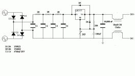
The PS looks O.K.
I would use a series reg myself followed by the shunt reg but that's just me.
Also, I suspect the Ox2 series of glowdischarge tubes to be quieter than their octal counterparts. It's a hunch though.
As for the heater supply, the CM choke does a better job when put in between the FWB and the first filter cap IME.
Cheers,
Hi,
If you're 12B4As are plate loaded by a resistor and you want to replace that with a CCS then I would put the CCS after the VR tubes.
It will than also reject any residual noise from the PS and VR tubes.
I understand this is for a linestage but what circuit do you have in mind?
Cheers,
I was thinking about putting a CCS infront of the VR tubes.
If you're 12B4As are plate loaded by a resistor and you want to replace that with a CCS then I would put the CCS after the VR tubes.
It will than also reject any residual noise from the PS and VR tubes.
I understand this is for a linestage but what circuit do you have in mind?
Cheers,
Frank,
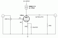
This is the preamp circuit as it stands now. The whole linestage (PS, fillaments, audio circuit) are as shown with the above and below schematics. I'm still chasing a little hum, which I expect is due to either layout or the volume pot....
Series regulator in the PS eh?
This is the preamp circuit as it stands now. The whole linestage (PS, fillaments, audio circuit) are as shown with the above and below schematics. I'm still chasing a little hum, which I expect is due to either layout or the volume pot....
Series regulator in the PS eh?
Attachments
Hi,
No need for it really....
You have the chokes which are way overdimensioned but I guess you know that already and the VR tubes operating as a shunt reg.
Nice PS in anyone's book, I think.
What does worry me but it's probably just a drawing mistake, is the 490R resistor as the gridleak on the 12B4A.
Surely that should read 470K or thereabout?
Also keep in mind that volpots really don't like DC on their wiper so either a switched attenuator or coupling cap are the safer solutions.
Cheers,
Series regulator in the PS eh?
No need for it really....
You have the chokes which are way overdimensioned but I guess you know that already and the VR tubes operating as a shunt reg.
Nice PS in anyone's book, I think.
What does worry me but it's probably just a drawing mistake, is the 490R resistor as the gridleak on the 12B4A.
Surely that should read 470K or thereabout?
Also keep in mind that volpots really don't like DC on their wiper so either a switched attenuator or coupling cap are the safer solutions.
Cheers,
Whoops.
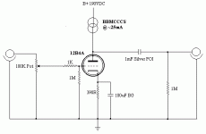
Thanks for pointing that out Frank. The grid-leak and the output bleeder are both incorrect. I have fixed the values.
I know the chokes are on the big side. They are rated at 20H 100mA. If I am only drawing a total of 45mA through the PS, would the total inductnace of the chokes be lower?
Thanks for pointing that out Frank. The grid-leak and the output bleeder are both incorrect. I have fixed the values.
I know the chokes are on the big side. They are rated at 20H 100mA. If I am only drawing a total of 45mA through the PS, would the total inductnace of the chokes be lower?
Attachments
Hi,
Fortunately not.
Cheers,
If I am only drawing a total of 45mA through the PS, would the total inductnace of the chokes be lower?
Fortunately not.
Cheers,
Frank,
Where is the DC coming from in this case?
What would be appropriate in value for the input cap?
lso keep in mind that volpots really don't like DC on their wiper so either a switched attenuator or coupling cap are the safer solutions.
Where is the DC coming from in this case?
What would be appropriate in value for the input cap?
Hi,
The grid is biased negative and tubes can and do fail occasionally.
Into a 1M impedance 0.100µF is already more than big enough...
I think I used 0.047µF for my CF.
Here's the equation:
f = 1/(2*pi*R*C)
Where f is the lowest frequency you want to pass, R is the input impedance, 1Meg in this case. C is what you're trying to resolve.
Cheers,
Where is the DC coming from in this case?
The grid is biased negative and tubes can and do fail occasionally.
Into a 1M impedance 0.100µF is already more than big enough...
I think I used 0.047µF for my CF.
Here's the equation:
f = 1/(2*pi*R*C)
Where f is the lowest frequency you want to pass, R is the input impedance, 1Meg in this case. C is what you're trying to resolve.
Cheers,
Hi,
There's nothing to calculate...You picked a 1 Meg Ohm gridleak resistor and that's what the cap sees.
So here Rin = Rg
Cheers,
How did you calculate the input impedance in this case?
There's nothing to calculate...You picked a 1 Meg Ohm gridleak resistor and that's what the cap sees.
So here Rin = Rg
Cheers,
Hi,
Most of the time it's a work or fail situation.
It doesn't normally happen but better safe than sorry.
Correct.
Cheers,
So, it the tube were to fail, would it be an instantaneous event, or would small amounts of DC appear periodically with time?
Most of the time it's a work or fail situation.
It doesn't normally happen but better safe than sorry.
I take it the cap is to protect the pot, but if I were using a stepped attenuator, this would then be unnecessary, correct?
Correct.
Cheers,
Hi Bryan
The 1 MOhms (Safety) grid leak, as in this circuit the efectif grid leak is the 100 K pot and the 1M is only for safety in case of bad contact in the pot.
This 1 M Ohms grid leak is best connected in the left side of the 1K Ohms grid stopper...as in that case only one connection is done in the grid input pin (the 1k resistor).
Hey guys,
I have a quick question......
With respect to the 12B4A, do I need 2 grid leak resistors, as the grid has two connections. Currently, I have 2 1K grid stopper resistors, one connected to each pin, and then joined together at one point for the input. I have one grid leak resistor, coming from only one of the grid connections.
I hope this question makes sense, I will touch up the schematic to include this later tonight when I get home.....
Thanks,
Bryan
Hi,
Just one, the pot, is fine.
That's fine.
Cheers,
With respect to the 12B4A, do I need 2 grid leak resistors, as the grid has two connections.
Just one, the pot, is fine.
Currently, I have 2 1K grid stopper resistors, one connected to each pin, and then joined together at one point for the input.
That's fine.
Cheers,
Don't use more capacitors after rectifying !
4 x 3700uF -> 1 x 100000uF (!) with corresponding coil protecting the rectifier diodes from too high current when you turn on the device performs extremely well (enormous reserve for ultra-fast and strong performance-peaks).
Not a lucky idea using more caps, they're all different. The smallest capacitance will get the highest voltage, the biggest the lowest voltage. You can compensate this by parrallel-connected resistors, but it's still not the best you can get. (The capacitors will have the same Q where Q = C x U).
So try to use one huge cap there, be sure of it's high quality.
- Status
- This old topic is closed. If you want to reopen this topic, contact a moderator using the "Report Post" button.
- Home
- Amplifiers
- Tubes / Valves
- Pre PS Improvements?


