Still in the planning phase, considering various options for my power amp project (thanks for the suggestions guys!).
I was thinking of building a ST-70 design using an Edcor transformer, mainly the CXPP30-6.6k. A470 transformers are a little more than I'd like to spend given that I'm relatively new to this. What are the downsides to using a 6.6K 30W Edcor as opposed to the A470? Any changes I'd have to make to the design?
Also, would using a 30W transformer be a problem for this? I'm okay with running at slightly lower power than the 35W the ST-70 originally made.
Would I be better off doing this design using the 6.6k Edcor?
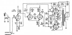
Mullard EL34 Push-Pull Tube Amp Schematic (Dynaco A420 Transformer)
I've also heard a lot about the El Cheap Grande amp on this forum, but have failed to find a (working) link to a schematic.
Mullard EL34 Push-Pull Tube Amp Schematic (Dynaco A420 Transformer)
I've also heard a lot about the El Cheap Grande amp on this forum, but have failed to find a (working) link to a schematic.
In a push-pull transformer for an amp with a lot of negative feedback (like the ST-70), it helps to have very high bandwidth. I found that the Edcor push-pull transformers fell apart pretty early up top, certainly using A470 clones will give you better results. (they cost more for a reason)
If you triode strap the EL34s, you can remove the negative feedback and not worry so much about high frequency instability.
If you triode strap the EL34s, you can remove the negative feedback and not worry so much about high frequency instability.
I have not had good results with the bandwidth available from Edcor's PP output transformers.
Interesting. Yet if the archives are scanned, info. from a member who successfully executed Williamson style circuitry using Edcor "iron" can be found.

Also, what do you mean by "triode Wire finals"?
Triode wiring means connecting the screen grid of a multi-grid type to the plate by either wire or a small resistance. Triode wiring always lowers the internal impedance of the tube and very frequently improves linearity. That's the good. The bad is that power O/P is halved or worse.
-----------------------------------------------------------------------------------------------------------------------------------------------------------
Mullard style circuitry, like that previously linked, is an excellent choice. However, EICO's HF89 is (IMO) a better starting point. You will use the Edcor CXPP60-4K and AnTek AS-3T325 "iron" previously linked.
Notice the dissimilar plate resistors in the 6SN7 long tailed pair (LTP) phase splitter. That's a crude technique for establishing balance between the 2 sides. The modern method is to replace the "tail" resistor (R15) with a constant current sink (CCS) and use 1 value for the 2 plate resistors. The low cost 10M45S suits this role well. You will use this part as R11 and R13. The inductance of that wirewound part will cause an increase in gain as frequency rises, which will compensate for the HF performance issue AW mentioned. Give with 1 hand and take away with the other.
") FWIW, the technique is called "peaking",
FWIW, the technique is called "peaking",The triodes in the 6SN7 and 6CG7/6FQ7 are "identical". It's your choice between the 2 types.
A decent multi-meter is absolutely essential. Do you have access to an oscilloscope? No access can be worked around, but brute force techniques will be employed.
More "mouthfuls" to follow.
Attachments
I was thinking of building a ST-70 design using an Edcor transformer, mainly the CXPP30-6.6k. A470 transformers are a little more than I'd like to spend
I think if you'll look into using KT-66 instaed of the EL34 you'll have a superb amp. Just the right power and Z for the trannies. Just put the recommended screen grid stoppers in the UL tap leg and it'll sing all day long.
Last edited:
Interesting. Yet if the archives are scanned, info. from a member who successfully executed Williamson style circuitry using Edcor "iron" can be found.
I couldn't get much in the way of a 10kHz square wave out of them. The ringing was pretty extreme, and it was a major compromise between taming the ringing and maintaining the square-ish shape to the square waves.
I've worked with A470 and Z565 clones withoyt running into these issues.
Thanks for the suggestion. Would you recommend this over a Dynaco ST-70 design with Edcor transformers? Yes, I do have good meters and an oscilloscope.Mullard style circuitry, like that previously linked, is an excellent choice. However, EICO's HF89 is (IMO) a better starting point. You will use the Edcor CXPP60-4K and AnTek AS-3T325 "iron" previously linked.
I definitely prefer Mullard style to Dyna style. Dyna style uses a "concertina" phase splitter and the peaking tweak could easily fail to work. A "concertina" phase splitter is a tricked out voltage follower, with lots of local current NFB.
IMO, the "budget" O/P tube to use is the ElectroHarmonix (EH) 6CA7. Don't get Eboned. Buy from a reputable dealer, like Jim McShane.
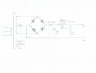
H713, I want you to draw and upload a schematic for the basic B+ PSU. Parallel the 325 VRMS windings of the AnTek power trafo and bridge rectify with 4X Cree C3D03060F Schottky diodes. CLC filter the "raw" B+ with 2 of these caps. and this Edcor choke. Insert a CL-130 inrush current limiter, in the "hot" line, between the O/P of the bridge rectifier and the CLC filter.
Later on, we'll deal with subsidiary B+ voltages/decoupling networks. We'll deal with the negative bias supply later too. Hint, AnTek saves "scratch" again.
BTW, as you are finding out, magnetics are the big ticket items in a tube amp build.
IMO, the "budget" O/P tube to use is the ElectroHarmonix (EH) 6CA7. Don't get Eboned. Buy from a reputable dealer, like Jim McShane.
H713, I want you to draw and upload a schematic for the basic B+ PSU. Parallel the 325 VRMS windings of the AnTek power trafo and bridge rectify with 4X Cree C3D03060F Schottky diodes. CLC filter the "raw" B+ with 2 of these caps. and this Edcor choke. Insert a CL-130 inrush current limiter, in the "hot" line, between the O/P of the bridge rectifier and the CLC filter.
Later on, we'll deal with subsidiary B+ voltages/decoupling networks. We'll deal with the negative bias supply later too. Hint, AnTek saves "scratch" again.
BTW, as you are finding out, magnetics are the big ticket items in a tube amp build.
The cheapest source I've found, and I can get there in 30 minutes. They also tend to underrate their transformers. Hammond Push-Pull Tube Output Transformers - (1608 - 1620, 1645 & 1650 Series)
Sorry about the hand drawn Schematic. Hopefully I'll have time to draw it up in a proper schematic editor tomorrow.
That's very neat and fancy/shamancy is not needed. When I draw, hen scratches are produced. There are some minor corrections. The choke's 350 mA. rating is the limiting factor in this setup. 350 mA. is way more than the absolute minimum needed. Reserves of current allow for dynamic headroom and superior bass performance.
The AnTek AS-3T325 has pairs of secondaries. Connect the 325 V. windings in parallel. Remember, when cap. I/P filters are employed, approx. 1/2 of the RMS current is available as DC. Allocate a separate filament winding to each channel.
The filter caps. are 330 μF., not 350 μF.
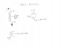
I'm uploading a sample of my poor handiwork. We will come back to that sort of topology, when we work on negative voltages. Of course, you will build with 100% Schottky diodes. Coincidentally, what you will build also has a low current "tall" rail and a high current "short" rail.
Attachments
- Status
- This old topic is closed. If you want to reopen this topic, contact a moderator using the "Report Post" button.
- Home
- Amplifiers
- Tubes / Valves
- ST-70 with Edcor Transformers