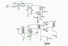
I'm looking to build this amp out of the parts I mostly have on hand (a few ICs are missing). It is a mashup of my 6B4G Dynaco based output section, the Impasse voltage regulator and CCS for the driver, and the Amity for the signal path via input and interstage transformers. It would all be built onto my ST-70 chassis where much of the circuit already exists. I would mostly replace just the driver board, and even there I would keep the VR since the Curcio driver I have was adopted for the Impasse as well. The driver tube itself would be the cheap and plentiful 6N6P, also already being used in the Curcio board in place of a 6DJ8. It would all fit, with the big transformers on the top and the little 1544a underneath.
I still have to determine some resistor values but that is about it. It all seems too simple to me, but I've been looking at these designs off and on for years without actually building anything. Truth be told I'm still happy with what I have but need something to do. The additional cost to build won't exceed $50, so that isn't an issue.
Please excuse any misuse of symbols as I've never used the software before. I couldn't find a DHT symbol either. Also I've excluded the power supply, but it is still an ST-70, with maybe some small mods that Curcio included in his quad cap replacement board. No selenium rectifier either, that was for bias IIRC, and I'm using cathode bias.
Any comments/advice?
Attachments
I used to use 6N6Ps in my differential transformer coupled line stage (50mA@150V) and they would last ~6 months. Switched to 6N30s, last 2 years and sound better. Granted they are more expensive and you will also have to screen for matched pairs (same as with the 6N6Ps). Also, a neg. grid bias of ~6.5-7V creates more dynamic headroom.
The CCS in series with the CT of your interstage transformer isn't serving any purpose. You could use the CCS to feed a VR 75 + VR150 regulator tubes in series to make +225V regulated for your driver.
If you have two 6V windings and you use two separate cathode bias resistors/caps, then you get nice DC current balance through your OT.
You could dump T3, ground one grid of the 6N6 and put a simple CCS under the common cathodes. This will improve amplifier performance and drop the cost considerably.
You are running the 6N6 too hard. Increasing the bias voltage would give more compliance to a CCS/differential amp, so that's worth considering.
If the voltage regulator and CCS are all crammed onto a module and you must use them, you could setup the 6N6 as paralleled voltage amplifier that's CCS loaded then use the interstage transformer as a parallel feed phase inverter.
The CCS in series with the CT of your interstage transformer isn't serving any purpose. You could use the CCS to feed a VR 75 + VR150 regulator tubes in series to make +225V regulated for your driver.
If you have two 6V windings and you use two separate cathode bias resistors/caps, then you get nice DC current balance through your OT.
You could dump T3, ground one grid of the 6N6 and put a simple CCS under the common cathodes. This will improve amplifier performance and drop the cost considerably.
You are running the 6N6 too hard. Increasing the bias voltage would give more compliance to a CCS/differential amp, so that's worth considering.
Agree with all of this. Separate cathode resistors will be better at keeping things balanced versus a single anyway.
If you want the highest quality sound you need to worry about AC balance also. IMO the CCS belongs on the cathode were it can enforce AC balance. That will entail a negative supply and require matched tubes. As to a CCS fed shunt regulated B+ supply: VR tubes? Yuck! Look at the Salas shunt reg. or the K&K Audio version. It should be noted with this arrangement that as the tubes age the grid bias voltage will drop cutting into signal headroom. With the CCS on top as drawn the bias current and grid voltage are fixed; the current source will set the plate voltage and as the tube ages it will rise.
Driver or output? AC balance with a CCS negates the need to have matched triodes in the driver half. If 10V of bias is used, I would debate the need for a negative rail.That will entail a negative supply and require matched tubes.
It should be noted with this arrangement that as the tubes age the grid bias voltage will drop cutting into signal headroom. With the CCS on top as drawn the bias current and grid voltage are fixed; the current source will set the plate voltage and as the tube ages it will rise.
The grid voltage is too low as it is. Setting it closer to 10V will reduce plate dissipation a bit and provide some flexibility as the tubes age.
Let me ask my question a different way. Will it work? It sounds like I can then refine it from there.
For VR tubes, I have a quad of 0C3 that I could use (I was going to build the Amity from scratch, which uses these). And what was recommended above goes back to the same concept except slightly different values.
I don't have separate 6.3v windings to separate the cathodes of the power tubes, what I drew is what has been working for 10 years now.
I already have the transformers, so I will use the input phase splitter. I've been watching the Swap Meet and eBay and snapped them up when I saw them.
Since it took me years to get to this point, other priorities and all that, and this was to be my project for the winter and it is already February, maybe I'll just stick with it the way it is. I'll just give it a try on a breadboard and see how it sounds and take it from there. There really aren't that many parts.
That was 50mA total or 25mA/section. I used a cathode CCS "tail" with the B+ CCS fed shunt reg. The tubes would initially have ~-3V grid bias. When they were "done" it had dropped to less than -1V. 6 months to a year max.
Unless you need 25ma (I used a 6N6P to drive an interstage transformer flawlessly at 14ma) bias it colder and it'll last for years. The same thing happened with 6P1P with me. I biased them hot (18W, 50% over maximum) with an LM317 CCSink in the cathode. When I started they biased at -14V however, about 6 months later, when I sold the amp to a friend, they were only at -6V! Thing still sounded fine though, just less power. Of course I gave him a new set of tubes with it and showed him how to lower the bias current to whatever he liked.
EDIT: Just saw you don't like the sound of them running colder. 4 6N6P is cheaper than 1 6N30P though...
Last edited:
First you regulate the voltage. Then you regulate the current. Then you put it on a big capacitor which smooths the voltage. By this point the electrons don't know what to do! Well, actually they will do what they want to do.
Will it work? Yes.
Is it a total waste of low-cost Silicon? I say it just makes more build-time (and more ways to go wrong) without any likely audio advantage. (But it is your baby, and everybody's baby is beautiful to the parent.)
_I'd_ replace 30 connections with 2.
Will it work? Yes.
Is it a total waste of low-cost Silicon? I say it just makes more build-time (and more ways to go wrong) without any likely audio advantage. (But it is your baby, and everybody's baby is beautiful to the parent.)
_I'd_ replace 30 connections with 2.
Attachments
First you regulate the voltage. Then you regulate the current. Then you put it on a big capacitor which smooths the voltage. By this point the electrons don't know what to do! Well, actually they will do what they want to do.
Will it work? Yes.
Is it a total waste of low-cost Silicon? I say it just makes more build-time (and more ways to go wrong) without any likely audio advantage. (But it is your baby, and everybody's baby is beautiful to the parent.)
_I'd_ replace 30 connections with 2.
I don't think the build time will be much in any case. And the cost is pretty small too. Whether it makes a difference or not is really the only issue. But you are right in that I could put it together without that and it would also work, and maybe I will. The VR is already in place so just drop the CCS. I could always add it later.
- Status
- This old topic is closed. If you want to reopen this topic, contact a moderator using the "Report Post" button.
- Home
- Amplifiers
- Tubes / Valves
- What do you think of this mashup amp?