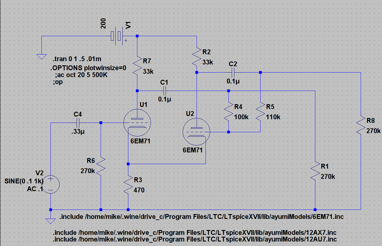
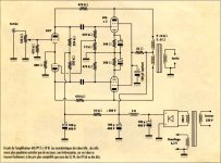
Looking at doing a Class A PP 6EM7 using floating paraphase (don't ask me why). Thoughts on this implementation? B+ is pretty much a given as is my desire to try this kind of PI.
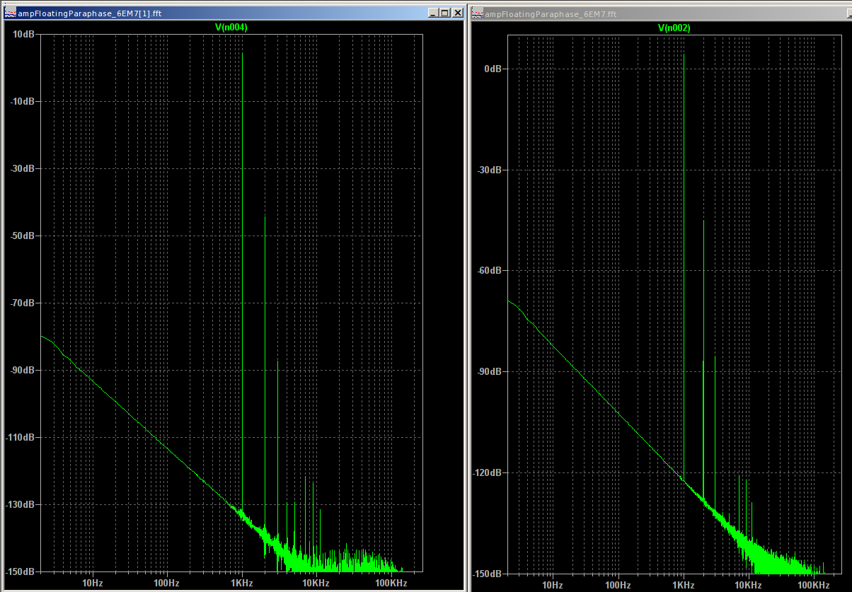
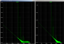
Distortion plots being notoriously suspect it is none the less interesting how little the spectra differ.
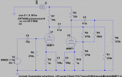
This bias point puts plates at 148v, Cathodes at 1.48v, Cathode current at 1.58mA.


Distortion plots being notoriously suspect it is none the less interesting how little the spectra differ.
This bias point puts plates at 148v, Cathodes at 1.48v, Cathode current at 1.58mA.
Attachments
Interesting, many people here seem to be allergic to the paraphase splitter. It is not difficult to find arguments to choose other solutions, although there are several designs and products out there with happy owners. Personally, I would welcome a good discussion on implementation, pros and cons of the paraphase phase splitter. The Valve Wizzard page has a good primer.
Your implementation of the floating paraphase seem to be rather similar to that used by Erik Andersson in the Audio Innovation 500 and 800 series (ecc88 and ecc82 implementation respectively). For example like here http://www.erikasson.se/schema/ai800.gif
I notice that the cathode resistor is not de-coupled, which make me wonder what the gain advantage is compared to an LTP implementation.
In the design found here: Menno van der Veen, audio electronic research & consultancy the gain triode and the inverting triode has separate resistors and the gain stage has cathode resistor de-coupled. Presumably to increase gain.
Menno offers a couple of interesting observations:
1 - Gain triode and inverter stage offer different output impedance. Therefore he made the grid resistor of gain stage adjustable in order to maximize PSRR and equalize the source resistance feeding the output tubes.
2 - He made the feedback resistor for the inverter stage adjustable in order to ensure optimal balance
3 - He also included a trimmer for Left/right balance. Probably to compensate for gain variation due to lack of global NFB.
All in all an LTP implementation would probably be better for new designs, still a discussion for tweeking and improving existing designs would be interesting.
Questions I have asked myself without finding an answer is - Can the common cathode resistor in your design be replaced by a LED biasing to improve gain and distortion? What happens if the output tubes start drawing grid current? Should the feedback resistors have their own capasitors to isolate them from the output tube grids etc? What are the distortion contribution of the inverter stage and how can it be minimized. How would the difference in frequency respons between inverting and non-inverting output effect sound?
Last edited:
For giggles I ran a sim with 100u cathode bypas and only difference was extended high freq resp. Also tried separate Rk with only VAS bypassed and again no increase in output but phase balance worsened.
RE LTP it would be difficult to achieve with only 200V B+. And of course would negate desire to try para.")
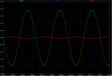
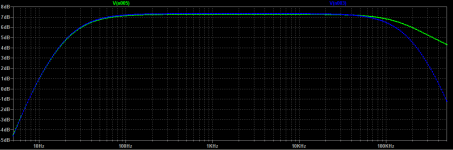
Since the response does not start to diverge until about 70kHz I am fairly confident that it will not be audible.
RE LTP it would be difficult to achieve with only 200V B+. And of course would negate desire to try para.
Since the response does not start to diverge until about 70kHz I am fairly confident that it will not be audible.
Last edited:
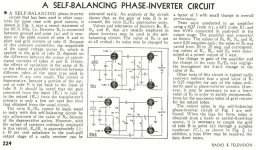
1. R3 gives a (very) little feedback 'between' U1 and U2. That somewhat linearizes the 2nd harmonic of U1, and tends to make the resultant amplitude of the 2nd harmonics of U1 and U2 to be somewhat closer in amplitude to each other (they're in opposite phase).
1a. If you put a bypass cap across R3, then:
U2's 2nd harmonic is canceled because it is driven by U1's 2nd harmonic, which is in the opposite phase of the 2nd harmonic of U2.
The result is U1 drives the "Push" stage with 2nd harmonic,
but U2 drives the "Pull" stage with No 2nd harmonic.
That is a disadvantage of this phase splitter, because the 2 output stages are driven by different amounts of 2nd harmonic distortion.
The advantage of this splitter is more gain, and more maximum output voltage to the next stage before clipping.
How much 2nd harmonic is dependent on how much drive the "Push" and "Pull" output tubes require. If little drive is required, there is very little 2nd harmonic from U1 (but remember, even less from U2).
2. Another type of dual triode phase invertor is with common cathodes that are biased by a common current source (LTP) (& with the 2nd grid grounded).
It will have the 2nd harmonic intrinsically cancelled from both in-phase and out-of-phase outputs.
The disadvantages of that kind of phase invertor is that the gain is reduced (never more than 1/2 u),
and that there is less maximum output voltage before clipping for the same cathode to grid bias as the above "serial' invertors (1 and 1a above).
Last edited:
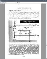
With due respect that is not the true floating paraphase inverter.
See RHD 4 or Crowhurst for the correct implementation and do not use some bastardisation. The floating paraphase inverter is the only one I'll use. For starters you do not need exact balance between the two halves, you can even use one part a triode and the other part a pentode for all that one cares.
People will say that it does not balance properly but that is bollocks - just add a small trimpot and then you can balance perfectly, better than the socalled "balanced double triodes" that you buy. Secondly, what about the following stages? Just hook up a distortion factor meter, disconnect the feedback and adjust the output for the lowest distortion. That takes care of differing amplification factors in the following tubes after the phase inverter. I no longer get riled up by the crappy matching that happens these days. 7% difference in signal is acceptable, less is better.
You can easily half the amount distortion in this way.
Attachments
-
 258nh2u.jpg66.6 KB · Views: 262
 -
 RCA 1940_08.jpg136.2 KB · Views: 233
 -
 RDH4 floating paraphase.png642.1 KB · Views: 264
 -
 Crowhurst paraphase 2.png487 KB · Views: 222
 -
 Crowhurst paraphase 1.png530.2 KB · Views: 234
 -
 AudioNote5.jpg226.7 KB · Views: 265
 -
 Scott 99D_5_6s.jpg722.3 KB · Views: 207
 -
 audio_note - P1 PP question mark.gif15.7 KB · Views: 228
Last edited:
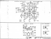
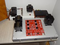
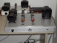
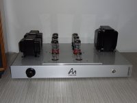
This is the last amplifier I build. It is partly based on the old Sansui which is a cult amplifier in Japan. If I had found the Sansui schematic before the Audio note schematic then I might have built that as I like octal tubes. Don't ask me why.
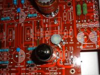
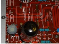
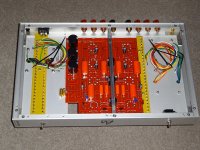
I used a PCB that I found on ePray, modified it and used a chassis from landfallsystems.com since I am no longer allowed / able to undertake any streneous activities. I use a separate cover plate so that I can easily make changes without having to remove the PCB.
You can see where I implemented the adjustment for the floating paraphase inverter. You can either pull the 6SN7 and feed a signal to the 12AX7 and then measure the voltages at the grids of the 6SN7 - easiest is a double beam oscilloscope, invert one signal and overlay. When the overlay becomes one line then it is perfect. Better is to disconnect the feedback and then adjust at approx 70% output for perfect output signal. Then when you put the feedback on (about 8 - 9 dB) you'll find distortion more often than not halved when compared to just having a perfect PI. But when you adjust at the output do not change your tubes around as distortion will go up. The PI tube is the important tube for tone and the output transformer is the other important part. I oversize the output and mains transformers by at least 50%.
Attachments
-
 DSC00861 small.jpg168.7 KB · Views: 163
 -
 DSC00866 small.jpg904.9 KB · Views: 125
 -
 DSC00900 small.jpg229.7 KB · Views: 91
 -
 DSC00902 small.JPG197.1 KB · Views: 133
 -
 Audio Note kit4 schematic as build.gif196.3 KB · Views: 218
 -
 DSC00864 small.jpg239.9 KB · Views: 206
 -
 DSC00928 small.jpg182.1 KB · Views: 103
Last edited:
Amedeus is it just the R from the junction of R4 and R5 to ground that I am missing? I admit that I am getting a little confused with the Crowhurst circuit due to the fixed bias.
No, it is the shared cathode. A true floating paraphase inverter can have two totally different tubes which cannot be the case if you have a shared cathode. Be aware that a cathode that is not bypassed has negative feedback, the 12AX7 drops from approx 40x amplification to approx 14.2x according to my calculation. The drawback is that when you do not bypass the cathode-heater leakage can give hum so you have to use a tube with little leakage. On another note: the 6SN7 is about the most linear double triode that you can find, I like that tube a lot.
edit: I do not like fixed bias. That is fine if you want maximum power output but you run the risk of shortened tube life and higher distortion, especially if the tubes are not well balanced. I cannot find the article anymore (but am certain about it since I queried the Audio Note setup) but for the least distortion Mullard recommended to bias the output PP a bit more towards class B than the normal AB recommended and to use individual cathode resistors.
Last edited:
edit: I do not like fixed bias. That is fine if you want maximum power output but you run the risk of shortened tube life and higher distortion, especially if the tubes are not well balanced.
This surely doesn't hold true universally! Fixed bias usually means small cathode currents and about two thirds of the plate dissipation rating at idle, whereas cathode bias means both full cathode current and full plate dissipation - at idle!
Best regards!
No, it is the shared cathode. A true floating paraphase inverter can have two totally different tubes which cannot be the case if you have a shared cathode. Be aware that a cathode that is not bypassed has negative feedback, the 12AX7 drops from approx 40x amplification to approx 14.2x according to my calculation. The drawback is that when you do not bypass the cathode-heater leakage can give hum so you have to use a tube with little leakage. On another note: the 6SN7 is about the most linear double triode that you can find, I like that tube a lot.
edit: I do not like fixed bias. That is fine if you want maximum power output but you run the risk of shortened tube life and higher distortion, especially if the tubes are not well balanced. I cannot find the article anymore (but am certain about it since I queried the Audio Note setup) but for the least distortion Mullard recommended to bias the output PP a bit more towards class B than the normal AB recommended and to use individual cathode resistors.
Thank you that clarifies it well.
In this case being 6EM7 based the VAS/PI tubes will be the same type by definition. In simulation a 1V peak input swings over 20V peak which in theory should be enough as the output tube bias point is likely to be around -20V and I thought the NFB would be good for linearity. I will investigate the other approach and see what happens.
For the heaters I was planning either elevated heaters or DC depending on what I have on hand (still checking my inventory).
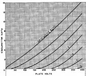
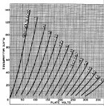
The output stage is to be biased class A the PS for the output stage is limited to about 130V-140V so I was considering mixed bias. I have to spend more quality time with the curves and see.
Later on I will probably play with disparate tube types as well since I find the whole thing quite fascinating (yes I am a bit quirky but it is a hobby because it is supposed to be fun right?
).The whole thing makes me wonder about something really quirky like a self split output stage using two different tube types.
Attachments
On small power amplifiers I usually use this acrosound circuit.
For higher power amps I use split phase (cathodyne), and I've never used an LTP.

Thank you for joining in. Interesting circuit. What is the reason for different bias points for the two halves of the AX7?
This surely doesn't hold true universally! Fixed bias usually means small cathode currents and about two thirds of the plate dissipation rating at idle, whereas cathode bias means both full cathode current and full plate dissipation - at idle!
This isn't necessarily true, but I will agree that if you are designing a class B push-pull amp, you can have very low PD at idle and you'll need fixed bias by design.
It's not impossible to design a cathode biased output stage that runs at 2/3 PD.
With R1 and R8 to ground, R9 is useless, even contra-productive (makes the open loop gain of the x(-1) stage smaller).Is this more proper?
And one cathode resistor without decoupling capacitor.The two triodes function with opposite phase, current in the cathode resistor doesn't change.If it does change the circuit is out balance.In that case, since the circuit is a (not very long)LTP, there is some correction.
Mona
With R1 and R8 to ground, R9 is useless, even contra-productive (makes the open loop gain of the x(-1) stage smaller).
This resistor, in line with the voltage divider between both anodes, appears to be essential with the original Floating Paraphase idea. Their value shold be much smaller w.r.t. the following stage's grid leak resistors, though.
Best regards!
- Status
- This old topic is closed. If you want to reopen this topic, contact a moderator using the "Report Post" button.
- Home
- Amplifiers
- Tubes / Valves
- 6EM7 Floating Paraphase (I know humor me please)