Hello everyone!
After making two successful push-pull transformers, I just finished my first 10W SE OPT to use with a fixed-biased KT88.
I now use a much better insulation, and my winding technique has improved.
I used a simple p-S-P-S-p sectionalization and 0.4mm insulation between windings.
The measurements seem good:
- DC resistance, primary = 93.62 ohm, secondary = 0.39 ohm.
- Leak inductance = 6.3 mH (1kHz)
- Pri/sec capacitance = 500 pF.
- Voltage ratio = 18.73
- Impedance ratio is 350.68, and reflected impedance is 2800 ohm for an 8 ohm speaker (I designed it for 2700 ohm, so it is close enough).
- UL tap is at 25%. I checked the ratio with AC multimeter and also an oscilloscope.
- Bandwidth, with 600 ohm signal generator, is 5.5Hz - 360 kHz. With this setup, the resonance is at 90 kHz, and the peak is not very high.
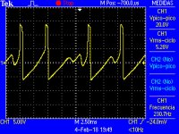
NOW, this is what I get (attached).
Connected to a test speaker, the sound is unbearable.
For the sake of completeness, I used .25mm wire for primary, and series secondary connection using 2x0.7mm wire, and 0.15mm gap.
I tested the amplifier with a commercial OPT, and works great.
Help is very much appreciated!!
After making two successful push-pull transformers, I just finished my first 10W SE OPT to use with a fixed-biased KT88.
I now use a much better insulation, and my winding technique has improved.
I used a simple p-S-P-S-p sectionalization and 0.4mm insulation between windings.
The measurements seem good:
- DC resistance, primary = 93.62 ohm, secondary = 0.39 ohm.
- Leak inductance = 6.3 mH (1kHz)
- Pri/sec capacitance = 500 pF.
- Voltage ratio = 18.73
- Impedance ratio is 350.68, and reflected impedance is 2800 ohm for an 8 ohm speaker (I designed it for 2700 ohm, so it is close enough).
- UL tap is at 25%. I checked the ratio with AC multimeter and also an oscilloscope.
- Bandwidth, with 600 ohm signal generator, is 5.5Hz - 360 kHz. With this setup, the resonance is at 90 kHz, and the peak is not very high.
NOW, this is what I get (attached).
Connected to a test speaker, the sound is unbearable.
For the sake of completeness, I used .25mm wire for primary, and series secondary connection using 2x0.7mm wire, and 0.15mm gap.
I tested the amplifier with a commercial OPT, and works great.
Help is very much appreciated!!
Attachments
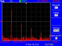
I've been taking some measurements of the amplifier/OPT, in search of core saturation, to validate my air gap. This is my first air gap, so I'm seeking for some feedback.
I've attached two scope captures.
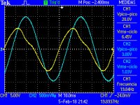
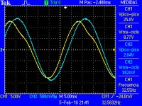
One is with output tube working in UL (25%), the other one is triode strapped.
Cyan is input signal.
Yellow is output (to an 8 ohm dummy load).
Both are very close to full power.
I decreased frequency, in search of core saturation (to validate the chosen air gap), until I got this distorted waves.
Are they showing core saturation? Or just inductive loading on the output tube?
With triode, it happends at a lower frequency, so it makes me think this is just the primary inductance loading the stage.
Is there any other way I can check my air gap?
I've attached two scope captures.
One is with output tube working in UL (25%), the other one is triode strapped.
Cyan is input signal.
Yellow is output (to an 8 ohm dummy load).
Both are very close to full power.
I decreased frequency, in search of core saturation (to validate the chosen air gap), until I got this distorted waves.
Are they showing core saturation? Or just inductive loading on the output tube?
With triode, it happends at a lower frequency, so it makes me think this is just the primary inductance loading the stage.
Is there any other way I can check my air gap?
Attachments
8W and 80 mA quiescent current.
It's a 0.15 mm aire gap. The sheet of insulation is 75 µm.
It gets down to 20 Hz, full power (triode strapped).
But I'd like to learn how to measure the saturation frequency, or the low cut-off due to the inductive loading of the primary.
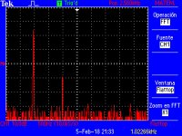
Attached, distortion for triode and ultralinear configuration, very close to clipping level.
Inside the amplifier, and using some 10 dB GNFB.
It's a 0.15 mm aire gap. The sheet of insulation is 75 µm.
It gets down to 20 Hz, full power (triode strapped).
But I'd like to learn how to measure the saturation frequency, or the low cut-off due to the inductive loading of the primary.
Attached, distortion for triode and ultralinear configuration, very close to clipping level.
Inside the amplifier, and using some 10 dB GNFB.
Attachments
Testing the transformer for things like bandwidth would require disconnecting the GNF.
If the transformer is the main limiter of bandwidth, that is the correct way.
(i.e. if bypass capacitors, coupling capacitors, and miller capacitance is not the limiter of the amp's bandwidth).
Here is a test for the aproximate primary inductance:
That does not include the effect of the operational (80mA) DC current in the primary.
Discharge all capacitors in the amp. Be sure they are discharged.
(and by the way, you should have bleeder resistor(s) across the B+).
But these take a long time to discharge, so check the voltage with a DMM
before jumping in with "hands and feet".
Remove the IEC power cord (and any other grounds that are connected to the amp).
Remove any and all loads from the transformer secondary, including the GNF resistor.
Then connect the 600 Ohm generator in Series with a 600 Ohms resistor, and connect that (1200 Ohm signal source) across the primary. Connect the scope across the primary (ground one end of the primary using the scope probe ground clip).
Set the generator to 1 kHz; measure the voltage across the primary on the scope, and record the voltage.
Set the generator to lower frequencies until the voltage is 0.707 x the 1 kHz voltage.
i.e. 10V at 1 kHz, 7.07V at a low frequency.
That is the -3 dB frequency (f) when the primary is driven from 1200 Ohms.
(1) 1200 Ohms = 2 x pi x f x L
(2) L = 1200 Ohms/(2 x pi x f). Solve for L.
Now, check the above answer by an independent measurement method:
Connect the 1200 Ohms signal source (600 Ohm generator in series with 600 Ohm resistor) across the primary.
Connect one channel's scope probe across the primary (the scope probe ground clip to one end of the primary).
Connect another scope channel's probe from the top of the 1200 Ohm source to the other scope probes ground clip (measuring across the series string of generator, 600 Ohm resistor, primary).
Starting at 1 kHz (the two channels may be fairly close to 0 degrees, but can be at another angle according to the self resonance of distributed C and primary L.
Lower the generator frequency until the phase angle difference in the 2 channels is
45 Degrees (1/8 of a complete sine wave).
That is where the primary inductive reactance is equal to 1200 Ohms.
That should be at or near the same frequency, f, that was calculated in (1) above.
Again solve for L by plugging in f into (2) above.
I estimate that the rp of the KT88 in ultra linear mode may be about 2000 to 3400 Ohms.
I estimate that the rp of the KT88 in triode mode may be about 1000 to 1700 Ohms.
Without GNF, that will result in the two different -3dB bandwidths you get in ultra linear
versus triode modes. It will also make a difference in the shapes of the low frequencies
versus UL and T modes, and the same shape will be at 2 different frequencies.
GNF will tend to bring the -3dB bandwidths, and shapes at low frequencies be a little closer to equal.
I hope that helps, and happy listening.
Last edited:
6A3sUMMER , thanks for you very detailed reply.
After some more study, I got some nice results.
Just to share them with you, here they are.
Primary inductance (measured under working amplifier, and dc current):
13.08 H
Core saturation frequency (at triode full output power):
20.2 Hz
Core saturation frequency (at -6dB full output power):
14.5 Hz
The low cut-off frequency due to inductive loading of the primary, is 34 Hz.
So the air gap is perfect!
If I increase it, primary inductance would fall, and with it, the low cut-off frequency would raise above 40 Hz, much before saturation effects come into play. Don't want that.
More primary turns would be needed to use a bigger gap, and get better bass response overall.
Or decrease primary impedance, which I can't (it is already low, near 2k5).
As I filled most of my winding window, this is my best right now.
So, I'm quite happy with this, my first SE OPT
Last edited:
Listening to my first SE OPT. Lacks bass and power.
I just finished a SE amplifier which uses my first handmade SE OPT on one channel, and another profesional OPT on the other.
My OPT seems great in basic tests using generator/scope, and it didn't saturate, even at 30 Hz, full power. Voltage ratios (anode, and UL tap), as expected.
Now, it doesn't sound really bad, but comparing it to the other pro OPT, there's a definite loss in bass and volume, and a bit "trashy" sound (though no distortion, and relatively clear voices).
I tried both ultralinear and triode modes.
I'm planning to dissasemble the enclosure to add some more gap, and re-test (I already did this in the scope test, and the gap seemed to be just fine, but this time I'd a listening test instead).
Appart from this, is there anything I could? Any advice?
Thanks!
Bass reproduction depends mainly on primary inductance
Lp = [4 π μ(eff) S Np²] / (9 l x 10⁸)
If you increase the gap
μ(eff) ≈ l μ / [l + l(gap) μ]
μ(eff) will decrease, and Lp will decrease too, making bass reproduction worse.
How did you calculate the number of primary turns?
The thread has changed!!!
Conclusions may change too.
How did you alculate the air gap? It seems too low now.
Last edited:
More primary turns would be needed to use a bigger gap, and get better bass response overall.
This is my guess too.
Hints (cgs units are used, except =Volts =Amperes)
i) With your lamination choice, determine Bac(max) and Bdc(max), in order to not saturates the core.
ii) Calculate the number of primary turns
Np = (Uac x 10⁸) / [√2 π fo S Bac(max)]
iii) Calculate the effective permeability, μeff, from here
Bdc(max) = [4 π μeff Np i(DC)] / (9 l)
iv) Calculate the air gap from here
lgap = l (μ - μeff) / (μ μeff)
As it is evaluated twice, for the real air gap (plastic sheet) you must divide it by 2.
v) Calculate primary inductance from here
Lp = (4 π μeff S Np²) / (9 l x 10⁸)
Last edited:
Apply tetrode mode ,open feedback loop, load 2.7k resistor across the primary, secondary unloaded, apply 1khz input until the primary starts clip. Now, with 20hz input adjust the air-gap for maximum excursion despite distortion on the primary . Load now the secondary instead, and measure with the same input level, the power bandwidth of your amp.
@Elerion - please do not start multiple threads on the same topic, which is against the Forum Rules.
Sorry. Will not happend again.
popilin, I agree with you, in that higher primary inductance helps bass reproduction, BUT a bigger gap does not mean less bass power.
A small gap leads to core saturation at low frequencies.
There's an optimun spot in the middle.
Anyway, I appreciate your detailed answer very much.
I already did tests like kokoriantz is suggesting, and the results were near perfect.
So, yesterday I did this: swap the anode taps of the two OPT, so they drive the opposite channel. And, guess what: now, my OPT sounds great, and the pro OPT sounds bad.
So it must be something with the circuit in one of the channels, even though they are the same, and share the same chassis. I checked and re-checked everything, but I might have missed something.
I swapped power tubes, and preamp tubes, problem persists.
The only strange thing I measured before connecting the amp to speakers, is that the the "bad" channel's preamp tube is a bit higher in idle anode voltage (190 vs 170 V), and that changing the GNFB trimmer seems to make almost no change in the output sine wave.
Both output tubes share the same fixed bias voltage. There's a single trimmer to tune it. Both tubes are nearly matched, and idle current is very close.
Today I'll remove GNFB and re check the circuit again.
Caps are correct values, and polarization.
Any guess?
popilin, I agree with you, in that higher primary inductance helps bass reproduction, BUT a bigger gap does not mean less bass power.
A small gap leads to core saturation at low frequencies.
There's an optimun spot in the middle.
I did not say that, what I sayd is
Bass reproduction depends mainly on primary inductance
You have a misunderstanding about the air gap
i) The air gap is mandatory in SE OPTs because it limits DC magnetic field and hence core saturation.
ii) The air gap is related to effective magnetic permeability and hence primary inductance.
iii) The air gap increases the linearity of transformer because (wel design is supposed) effective magnetic permeability is quite constant over the magnetic hysteresis loop.
A small gap DOES NOT leads to core saturation at low frequencies, and a big gap DOES NOT mean nor less bass power neither more bass power.
Transformer equations are consistent, and a correct calculation yields the correct air gap. If in the middle of calculation you do some guesstimates, obviously you must fine tune the air gap experimentally, DO NOT blame the equations.
If your lamination is not good enough, or your core choice is wrong, or your calculations are wrong, the transformer will pay the consequences, but DO NOT blame the air gap.
In the middle of my first reply, the thread was merged with a previous one, YOUR FAULT, and that affected conclusions.
Equations on post#16 where derived from Maxwell's equations and they were checked many times and used with total success, so use them with confidence.
You did not answer any of my requests, that is not a good attitude from someone asking for help, capisce?

Last edited:
- Status
- This old topic is closed. If you want to reopen this topic, contact a moderator using the "Report Post" button.
- Home
- Amplifiers
- Tubes / Valves
- Help troubleshooting my first SE OPT