Member
Joined 2009
Paid Member
I's a reference to the very old TV program, "What's My Line", where panelists tried to guess a mystery guest's occupation. Its iconic line (beginning of every show) was, "will the mystery guest sign in please", and the guest would write his name/occupation on a white board shown to the audience, but not to the panelists.
Member
Joined 2009
Paid Member
for Kitty Carlisle fans  - hear her sing in "Murder At The Vanities" Murder At The Vanities 1934 - Victor McLaglen, Jack Oakie, Kitty Carlisle, Carl Brisson, Duke Ellington, Gertrude Michael
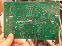
- hear her sing in "Murder At The Vanities" Murder At The Vanities 1934 - Victor McLaglen, Jack Oakie, Kitty Carlisle, Carl Brisson, Duke Ellington, Gertrude MichaelSo while trying to figure this out, I spotted some likely errors on the PCB. R21A has both ends connected to the bias supply rail, R21B appears to be correct (red elipses). There is also a strange difference between the two lower octal bases (I assume they should be very similar). The left base has a connection from R16A to pin 1, but nothing to pin 5. The right base has a connection from R16B to pin 5 but nothing to pin 1 (orange elipses). The assumption is that the filaments are always on pins 2 and 7 based on the silk screen and wired connections, and valves on the reverse side of the PCB as per the other photos.
I was trying to figure out the role of the transitors, but I struggled to accurately identify the tubes, and thought flagging the possible errors might be more helpful.
I tweaked the photo in Photoshop to make the underside tracks more readily visible.

I was trying to figure out the role of the transitors, but I struggled to accurately identify the tubes, and thought flagging the possible errors might be more helpful.
I tweaked the photo in Photoshop to make the underside tracks more readily visible.
Last edited:
Nope on all...
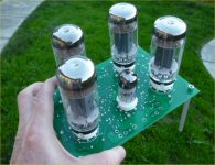
OK - so I missed the tube numbers in the first post for some reason... I think I was probably half asleep yesterday. I also counted the pins wrong (oh dear, never done that before). Of course, pins 4 and 8 on the 7591 are internally connected. Therefore my second point was completely wrong (my apologies).
But R21A is definitely not doing anything since both ends are connected to the same track...
Dremel is one approach, but I prefer to score across the track with a craft knife or similar with two cuts to create a narrow strip. Then the application of heat from a soldering iron to the isolated strip allows the copper to come away from the substrate very cleanly to create a neat break in the track.Dremel will save the day on R21A on the boards I have - layout is fixed with new rev. Thanks for spotting.
My Mouser order should come in today, so I can finish stuffing the board and get it on the bench. I'll probably end up using some Fisher 500B or 500C output transformers I have lying around. I also have some Sherwood iron that might work. First off, though, I'll be powering up the board with some bench supplies.
Cables & connectors & such are in place, and the output XFMRs have been fitted with connectors. Output transformers for the shakedown cruise will be a certain rusty pair (not so rusty, really) that George/Tubelab bequeathed to me a few years ago for the price of transport. I've never been one to say no to output iron... Tuesday, this beast will get slung onto the bench at work for a first power-up.
I just turned one of their brothers into a magnet. An arc from plate to ground, or the PC board plating that was formerly ground, now nonexistent, where the B+ was a 650 volt 1.7 amp power supply that has 1000 uF across it's output will do that.
Those transformers are 6600 to 0-4-8-16 ohms. They actually work better at 3300 to 0-2-4-8 ohms. I was pushing the meter north of 160 watts per channel through a pair when the insulation on a plate to plate feedback resistor broke down.
After cutting out the resistor and drilling out the charred PC board that channel was weak, distorted and drew too much current when driven hard. That's when I noticed that a screwdriver sticks to the OPT. I may try to degauss it when I find my variac.
- Status
- This old topic is closed. If you want to reopen this topic, contact a moderator using the "Report Post" button.
- Home
- Amplifiers
- Tubes / Valves
- Will the Mystery Amp Sign in Please?