Hi,
Got it from an old Philips book about tube manufacturing, it’s from 1946") Think you are right and most more modern small signal tubes have just a folded filament wire. But that is also a “bifilar” construction if you can say so. Some years ago there was debate if we should bias the filament below or above cathode potential for best sound but that discussion faded away without consensus. Concerning the hum in pre amps, I’ll stick with DC heater power also for indirect heated tubes.
Think you are right and most more modern small signal tubes have just a folded filament wire. But that is also a “bifilar” construction if you can say so. Some years ago there was debate if we should bias the filament below or above cathode potential for best sound but that discussion faded away without consensus. Concerning the hum in pre amps, I’ll stick with DC heater power also for indirect heated tubes.
Also in that book found something along these lines: A lot of the efficiency of coated cathodes depends on small amounts of metallic barium in the coating. When this metallic barium oxidises the efficiency dramatically drops. When the temperature is high enough the tiny oxide layer evaporates freeing the metallic barium. Maybe this is something why we must not run coated tube cathodes too cold (when filament voltage is low) ??? Still curious about a more extensive explanation of cathode “poisoning”.
Cheers
Got it from an old Philips book about tube manufacturing, it’s from 1946
Think you are right and most more modern small signal tubes have just a folded filament wire. But that is also a “bifilar” construction if you can say so. Some years ago there was debate if we should bias the filament below or above cathode potential for best sound but that discussion faded away without consensus. Concerning the hum in pre amps, I’ll stick with DC heater power also for indirect heated tubes.Also in that book found something along these lines: A lot of the efficiency of coated cathodes depends on small amounts of metallic barium in the coating. When this metallic barium oxidises the efficiency dramatically drops. When the temperature is high enough the tiny oxide layer evaporates freeing the metallic barium. Maybe this is something why we must not run coated tube cathodes too cold (when filament voltage is low) ??? Still curious about a more extensive explanation of cathode “poisoning”.
Cheers
cathode poisoning
this occurs when the space charge is low under low heating conditions, and the valve is passing current. Ions formed by the passage of electrons colliding with residual gasses ( There is always a few molecules of gas left) can then collide with the cathode surface and cause its eventual poisoning Apparently a poisoned cathode can be recovered by overheating by 20% untill emission returns, I havent tried with a poisoned cathode, just some dead of old age, but it does work!
the space charge is adequate at the +- 10% range of heater supply, and great gains in cathode life can be obtained at around 10% under heating on signal valves, where the current demands of the cathode are low. O/P valves should always be operated at as close to data sheet voltage as possible, or under extreame current use even around 5% higher than data sheet spec.
Pjotr said:Hi,
Usually filament voltage is specified as ±10% for regular tubes. But I was also told long time ago that too low filament voltage will shorten tube life either. Did that Mullard engineer also told you why Guido? Curious about it.
Cheers
Hi Pjotr
Yes, too low is no good, he advised never to go below -5% so 6.0V
In addition:
When not using tubes (standby), take away anode voltage, and switch the heater to ac, half of specified voltage.
When using DC when in operation, the polarity should be switched every month or so.
I have a Dutch report available of a conversation I organised with this engineer, it can be bought in Dutch only at
www.audio.nl
best regards
Digging up an old thread here rather starting fresh.
My Beard P50 power amp heaters are AC. ECC82 + EEC83 + KT88
I have no diagram but the AC appears to come direct from a secondary winding. I was getting 6.7acv which is on the high side. My mains comes in between 239-242v which is probably why the heater tap is a little high.
Today I have added an Isolation transformer. I was hoping it may also drop the volts a little. However, it is adding around 5v. I have not rechecked the heaters but I expect it has nudged this a tad higher.
What is the best way to bring the volts back towards 6.3v?
Thanks
If you don't already have one, add an inrush limiter on the primary side. You'll drop a volt or two on the primary. It might not be enough to drop the filament voltage though. The brute force approach would be to add low value, high wattage resistors between the secondary and the filaments.
S.
S.
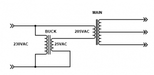
Here's a bucking transformer connection to reduce the voltages by about 10%.
A 12VAC transformer would reduce the voltages by about 5%.
The buck transformer's secondary current rating should be greater than or equal to
the main transformer's primary current rating.
A 12VAC transformer would reduce the voltages by about 5%.
The buck transformer's secondary current rating should be greater than or equal to
the main transformer's primary current rating.
Attachments
Last edited:
If you don't already have one, add an inrush limiter on the primary side. You'll drop a volt or two on the primary. ]
The power amp is AC to the heaters. My pre amp is DC.
Both would benefit from reduced inrush I think providing there are no negatives to this. I do hear a start up surge through the speakers a few seconds after power on and sometimes an over glow on the valves.
Where and what would I be best fitting?
.
I can't give you an exact answer as to which IRL to use. See the attached specs.
Choose an IRL that is rated a bit higher than the rating on your fuse. If your fuse is rated at say 4 amps, choose an IRL that has a 5 amp rating. The resistance decreases as the IRL warms up. Look at the table on the right side of the specs.
It will go somewhere between say the power switch and the transformer primary.
I don't think an IRL will give you all of the voltage drop you need. But it will give you a bit and provide of a soft start function.
You might need to add some resistance between the trans filament winding and the tubes. Hard to say exactly. I'd use two resistors, one on each lead from the trannie. You'll likely wind up with something between 0.1 and 0.5 ohms, likely with at least a 10 watt rating. Add up the total filament current drawn by the tubes and use ohms law to calc. the resistance needed. It might not give you exactly what you need but it will be a starting point.
S.
Attachments
You could add a fuse on the heaters,that might drop a few hundred millvolts. If all your valves are connected in parallel across the htr winding, you could try connecting one in series,the rest in parallel. Or how about parallel diodes, cathode to anode, anode to cathode, that should drop 0.4/0.6v, not sure about this last one.
Andy.
Andy.
Found this which suggests one option to use two diodes on one leg.
It also shows how to add a humdinger which I will try. I have a constant low level buzz out of the power amp which one possible could be the heaters?
The Valve Wizard
It also shows how to add a humdinger which I will try. I have a constant low level buzz out of the power amp which one possible could be the heaters?
The Valve Wizard
Few years ago I could have cited the paper from back in the day... still have it somewhere but the gist of the theory IIRC goes something like this:Still curious about a more extensive explanation of cathode “poisoning”.
At low filament voltages cathode might not necessarily get evenly heated and so certain spots or regions emit more than others. Then cathode current preferentially passes through small hotter spots, which get hotter so emit more so get hotter etc etc etc until the coating in that region degrades/evaporates and hence the 'poisoning'. Which is really a mix of evaporation and progressive degradation I suppose. Once a spot is consumed another takes its place, and so the cathode prematurely ages.
Same theory behind why B+ should be applied after filaments, and why rectifiers need to limit inrush current during warm up.
LD
Ahh,the diode dropper would work then, wasn't sure.
Humdingers/buckers work really well, you could also use the pot to drop any excess voltage by making it small enough in value. It would have to be a substantial pot though - 5w or bigger.
Andy.
I fitted a bridge rectifier to each mono side (uses separate transformers for each channel).
Its what I had in a draw. Wired as per the previous link.
With the Isolation transformer in place I rechecked heater voltage. It was 6.9vac. After fitting the rectifier I now have 6.1vac.
I also fitted 500r pots to add humdingers. Those don't make any difference to the low level hum I get.
Run out of ideas to reduce that. Its not loud but I can hear its presence with no record playing and a few meters from the speakers.
Maybe its as good as it will be. Given the amp now has all new components and is effectively two mono blocks yet the slight hum is equal.
under
https://www.tubecad.com/july2000/page10.html
I read this:
Purposely Running Low-Heater Voltages
We have covered over-voltages and their danger, but what of under-voltages: are they also dangerous? Many old textooks claim that any voltage lower or higher than the specified heater voltage will shorten the tube's life. A few sources offer a different view: namely, the higher the heater voltage, the shorter the tube life and the lower the voltage, the longer the tube life. Who is right? My guess is the second group, as I have experimented a little with lower heater voltages and I have found the tubes glow less brightly at turnon, which must be for the good. Besides it seems odd to me that a heater element would suffer from being under heated. I know of one pro-audio company that makes hybrid tube gear that uses a 5 volt power supply to feed all its 6.3 volt tubes. I have been told that the tubes work fine and last forever in these units. The following diagram from Richard Shea's "Amplifier Handbook" shows transconductance over time with three different heater voltages.
The first thing I noticed was that the 6.3 volts line fell off depressingly quickly: after just 10 hours or so the transconductance begins to slowly fall off at an amazingly linear rate. The 5 volt line, on the other hand, remains pretty much flat over the whole 5,000 hours of use. Why not try a 5 volt heater power supply and see if the extended life and greater consistancy in Gm, albeit lowr Gm, is not worth the effort. If you have had any experience with this approach, please drops an e-mail.
The fact, that shorter life expectancy occurs in case of heater voltages above 6V3 everyone understands straight away - but not at a lower heater voltage.
Obviously, other oxidation processes occur on the coated material of the cathode (cathode poisoning) while use with too low heater voltage, which unfortunately also shorten the life expectancy.
I. e. the heater voltage must have an exact value - which is ideal. Maybe additional dependent of the ambient temperature, because perhaps the cathode temperature is the actual value to consider.
In addition, it could depends not only on the type of the tube, but also from manufacturer and the year of manufacture.
Additional to the recommendation from the tube design engineer from Mullard (#6+23) I want to know more information in detail what happens, if heater voltage too low and how to find out, which value is ideal (easy to find out, if the right operating temperature of the cathode is known) and what spread is still acceptable (10% spread according several datasheets means already a fairly wide range between 5V7 and 6V9).
P.S.: a friend of me want to know this ideal heater voltage in case of the EL34 from JJ
https://www.jj-electronic.com/images/stories/product/power_tubes/pdf/el34_e34l.pdf
Last edited:
This is an issue I grappled with for my ESL direct drive amp.
The heaters of the output tube needed to be isolated to 2.5kV and I used 15W medical grade DC-DC converters with 10kV specified isolation.
I could not get 6.3V units, but I could get 5V units that I could uptrim to 5.7V.
That's what I use and so far no issues.
I believe it would become important if you run the tube at very high (max) Ia; each electron has to come from the heated cathode so then low heater could limit the max available current.
Sounds logical?
Jan
Heater voltage is one of several other aspects regarding service life of tubes - go to
https://www.diyaudio.com/community/...-on-variants-which-one-is-most-useful.403470/
https://www.diyaudio.com/community/...-on-variants-which-one-is-most-useful.403470/
TEK found that the tubes in the vertical amps of their 540 scopes had a problem called 'interfacing'.Still curious about a more extensive explanation of cathode “poisoning”.
A layer of material formed under the outer layer of emitting material, in circuit it looked like
a poor conduction layer in parallel with a capacitor under the surface.
The problem was fixed using 6DK6 tubes, my recollection there were 12 of those in the vertical amp.
The amplifier in this case is a PP Distributed design, something we won't find in audio.
But there could be tubes, both new & used that might have the 'Interface' problem.
Attachments
in this book are to find further advices:
Getting the most out of VACUUM TUBES, by Robert B.Tomer, published in 1960
http://www.tubebooks.org/Books/Atwood/Tomer 1960 Getting the Most Out of Vacuum Tubes.pdf
Getting the most out of VACUUM TUBES, by Robert B.Tomer, published in 1960
http://www.tubebooks.org/Books/Atwood/Tomer 1960 Getting the Most Out of Vacuum Tubes.pdf
http://www.tubebooks.org/Books/Atwood/Tomer 1960 Getting the Most Out of Vacuum Tubes.pdfI'm getting a 404 on that link.
(It's not really a serious academic book, take what it says with a grain of salt)
- Home
- Amplifiers
- Tubes / Valves
- Heater Voltage Range, Hi or Low