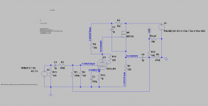
Please review my hybrid (6j1 tube + IRF530 mosfet) preamp, inspired by a ESP (Rod Elliot) circuit.
The simulated gain is around 2, and the THD is 0.005%.
I have most of the parts, so would appreciate a critical review before I take the plunge.
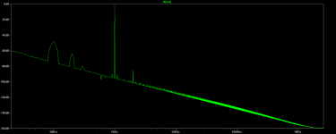
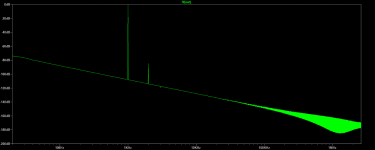
I have attached the FFT with a 1V ripple in the PS as well ( you will see a 100Hz bump).
Thanks.
The simulated gain is around 2, and the THD is 0.005%.
I have most of the parts, so would appreciate a critical review before I take the plunge.
I have attached the FFT with a 1V ripple in the PS as well ( you will see a 100Hz bump).
Thanks.
Attachments
I think a reasonable change would be to return feedback to the cathode rather than the grid, and having that much voltage with just a coupling cap at the output scares me a bit. Any plans for output DC and dethumping protection? In my experience with extremely similar circuits, you will get DC on your output during warmup without some sort of protection...
I think a reasonable change would be to return feedback to the cathode rather than the grid, and having that much voltage with just a coupling cap at the output scares me a bit. Any plans for output DC and dethumping protection? In my experience with extremely similar circuits, you will get DC on your output during warmup without some sort of protection…
Is the solution as simple as putting a 200 H choke in parallel with VOUT and ground? It has a reactance of over 27 kΩ at 20 Hz. Any lower Hz is squashed. Inductances are great at soaking up thumps.
Nominally, from 30 Hz to 30 KHz, it cuts itself out of being a current sink.
GoatGuy
Is the solution as simple as putting a 200 H choke in parallel with VOUT and ground? It has a reactance of over 27 kΩ at 20 Hz. Any lower Hz is squashed. Inductances are great at soaking up thumps.
Nominally, from 30 Hz to 30 KHz, it cuts itself out of being a current sink.
GoatGuy
It very well could be such a simple solution.
I had a few speaker protection boards from AMB at the time that I used, but chokes work too if you like them. Even a relay with a simple delay circuit works too.
auriga₂₀₀₁in;5314869 said:Please review my hybrid (6j₁ tube + IRF530 mosfet) preamp, inspired by a ESP (Rod Elliot) circuit.
The simulated gain is around 2, and the THD is 0.005%.
I have most of the parts, so would appreciate a critical review before I take the plunge.
I have attached the FFT with a 1V ripple in the PS as well ( you will see a 100Hz bump).
Thanks.
I say build it and see. It's clear that you're happy with your simulation skills. So, I'm not even sure why you're asking for comment. I might be inclined to question why you only want gain of 2× or +6 dB. But really, I'm not that interested: you surely DO have a reason, hence why you designed it that way.
So, give it a try.
Cobble it together "breadboard" style, knowing full well it'll be buzzy. But do it anyway, and use your digital oscilloscope and output from your PC headphone jack to provide signal. (there are thousands of oscillator apps that you can use as pretty good signal generators. For free.)
Then using a high-divisor probe (100× is good), capture that output. Don't worry: if your output is ±3V P-P, then your oscilloscope function should easily be able to show you accurate 30 mV sines. Do FFT on them. See what the real THD performance is (if you like). So much better than simulation!
BTW - why even have the tube at all? if you're going to use a MOSFET to act as a source-follower, then I fail to see why you're using a tube as the input element. You've clearly added so much negative global feedback as to 'denature' the tube's nominal E1.5 triode behavior (tetrode) behavior, so … to me it seems like a “see if it works, just to try it out” thing to begin with.
Again.
Build it.
Stimulate it. (no, not SIMulate it)
Measure it.
LISTEN to it.
It'll be a much more interesting discussion.
GoatGuy
Last edited:
It very well could be such a simple solution.
I had a few speaker protection boards from AMB at the time that I used, but chokes work too if you like them. Even a relay with a simple delay circuit works too.
True. I like the bûtt-stupid simplicity of chokes. They just "do their job". thanks (I mean it) for the input.
GoatGuy
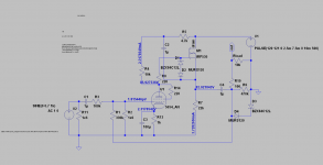
Updated schematic
Thanks Lingwendil, I will simulate the feedback to the cathode option and update. In the meanwhile, I have updated the current design with these mods:
- add a gate stopper to the mosfet
- upped the anode voltage
- upped the gain
- added zener + diode protection to the mosfet
- added zener + diode protection to the output
The regulated PS I am building starts slow (~ 3 secs) to reach 120V. Need to think some more on startup issues.
I am awaiting some parts to start building... will keep you posted.
I think a reasonable change would be to return feedback to the cathode rather than the grid, and having that much voltage with just a coupling cap at the output scares me a bit. Any plans for output DC and dethumping protection? In my experience with extremely similar circuits, you will get DC on your output during warmup without some sort of protection...
Thanks Lingwendil, I will simulate the feedback to the cathode option and update. In the meanwhile, I have updated the current design with these mods:
- add a gate stopper to the mosfet
- upped the anode voltage
- upped the gain
- added zener + diode protection to the mosfet
- added zener + diode protection to the output
The regulated PS I am building starts slow (~ 3 secs) to reach 120V. Need to think some more on startup issues.
I am awaiting some parts to start building... will keep you posted.
Attachments
I think a reasonable change would be to return feedback to the cathode rather than the grid...
No. Presumably he wants and needs NFB. Returning the FB loop to the tube's cathode would mean PFB and turn the amplifier into an oscillator.
Best regards!
- Status
- This old topic is closed. If you want to reopen this topic, contact a moderator using the "Report Post" button.
- Home
- Amplifiers
- Tubes / Valves
- 6j1 hybrid preamp