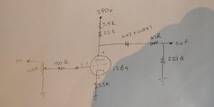
Recently I bought a DIY 12B4 preamp assembled by someone else. It needed some power supply work due to hum.
I've attached a schematic. Now I'm curious. Before I try it in my system I'm wondering if there could be issues with the design. I was going to rework it into a 12B4 pre posted by Kegger. I've posted Keg's schematic in the next post below.
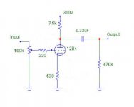
Here is the Keg pre I was gonna turn this into.
I've attached a schematic. Now I'm curious. Before I try it in my system I'm wondering if there could be issues with the design. I was going to rework it into a 12B4 pre posted by Kegger. I've posted Keg's schematic in the next post below.
Here is the Keg pre I was gonna turn this into.
Attachments
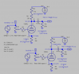
I know this is a little off topic but SRPP 12B4 is honestly the way to go if you can gather a good set of tubes that are not too noisy.
Salectric is right about the grid stoppers, I use 3.9K in the one I built, you could probably get away with even higher like 4.7K as well.
Biasing the 12B4 with a CCS on the cathode for around 15-20mA might be a good option to try if you feel up for it, I tried it myself when I was first playing around with the tube and had good results. I decided to go for SRPP in the end though. I can draw up a diagram if you want to experiment with a cathode bias CCS.
Also make sure you have a well filtered power supply, preferably with the power transformer well isolated from the tubes by means of bushings or something of sorts if it is not all ready.
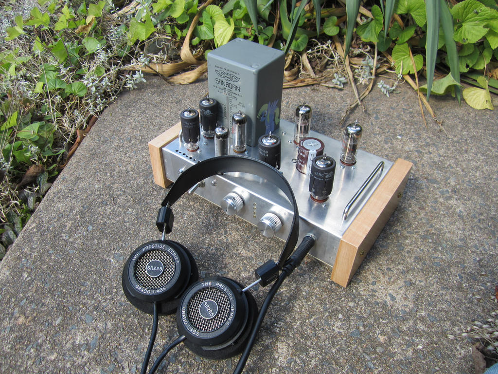
Let us know what you think about the sound of the 12B4, I am curious since I have not seen many people actually build a "fully working" preamp with this tube. For me I find that it is a very "transparent" sounding tube but also very mechanically "noisy" at times which apperently can be worse if you have them biased hotter (in the 20mA range which is what I have them approximately biased at with 250V regulated B+).
Hopefully this picture will inspire you a bit, if you like the tube and want to give SRPP a try I can provide you with the schematics of what I came up with, it's a far from perfect design but it is just a TV tube after all.
Salectric is right about the grid stoppers, I use 3.9K in the one I built, you could probably get away with even higher like 4.7K as well.
Biasing the 12B4 with a CCS on the cathode for around 15-20mA might be a good option to try if you feel up for it, I tried it myself when I was first playing around with the tube and had good results. I decided to go for SRPP in the end though. I can draw up a diagram if you want to experiment with a cathode bias CCS.
Also make sure you have a well filtered power supply, preferably with the power transformer well isolated from the tubes by means of bushings or something of sorts if it is not all ready.
Let us know what you think about the sound of the 12B4, I am curious since I have not seen many people actually build a "fully working" preamp with this tube. For me I find that it is a very "transparent" sounding tube but also very mechanically "noisy" at times which apperently can be worse if you have them biased hotter (in the 20mA range which is what I have them approximately biased at with 250V regulated B+).
Hopefully this picture will inspire you a bit, if you like the tube and want to give SRPP a try I can provide you with the schematics of what I came up with, it's a far from perfect design but it is just a TV tube after all.
I built two versions of 12B4 line preamp a while ago (still have some 12B4A BTW). There are plenty of informations here. For exemple, Salas did a design using LEDs and MOSFETs
12B4 Preamp
12B4 Preamp
")
Thank you all for your input! I had a listen to the original circuit and it sounds pretty nice. It's detailed and revealing, and more neutral than warm. No oscillation to be heard but I will change out the grid stopper resistors as suggested. The pre is driving my test bed system which is a Krell KAV300i and Alon Model II speakers, so pretty revealing.
I have limited space as the chassis was already drilled for the existing circuit. And the PS is set up 290v and would be a PITA to change. The chassis is 1/8" aluminum which the builder assembled out of pcs.
The pre has 100k Alpha volume pots one of which was a bit noisy in spots. I have a couple Alps mono pots which I'll install. I bought them from PCX.
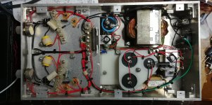
What you see from the pic is the power supply was designed with an 8a Hammond 12.6v filament transformer powering a reverse connected filament transformer. I couldn't see a name/brand on the second transformer. That big Hammond hums a bit. The PS itself also hummed when I got it. Since then I have done the following:
-built a divider to reference the Hammond filament CT to 26v. It was previously taped off
-isolated circuit ground from chassis ground with a circuit of bridged diodes/cap/10r5w resistor. In this pic the circuit is grounded at the star ground then a green wire at the star ground goes back to house ground.
-grounded house ground to chassis.
-added 100k/2w balancing resistors bypassed with 11nF MKT caps to the series e-caps
-added 1m/1w bleeder resistor bypassed with an 11nF MKT cap to the single B+ e-cap in the group of three caps
-installed an X2 cap across the line
After that the PS is quiet and the big Hammond transformer hum seems to be a bit quieter. That hum also slightly resonates through the chassis. I'll install some rubber washers to isolate the transformer from the chassis. Using screws/nuts/lock washers to assemble this chassis wasn't the best method. It should have been brake formed with mig/tig welded ends. I must say though, the builder did nice work and I know it would have taken a long time to put this together.
I have limited space as the chassis was already drilled for the existing circuit. And the PS is set up 290v and would be a PITA to change. The chassis is 1/8" aluminum which the builder assembled out of pcs.
The pre has 100k Alpha volume pots one of which was a bit noisy in spots. I have a couple Alps mono pots which I'll install. I bought them from PCX.
What you see from the pic is the power supply was designed with an 8a Hammond 12.6v filament transformer powering a reverse connected filament transformer. I couldn't see a name/brand on the second transformer. That big Hammond hums a bit. The PS itself also hummed when I got it. Since then I have done the following:
-built a divider to reference the Hammond filament CT to 26v. It was previously taped off
-isolated circuit ground from chassis ground with a circuit of bridged diodes/cap/10r5w resistor. In this pic the circuit is grounded at the star ground then a green wire at the star ground goes back to house ground.
-grounded house ground to chassis.
-added 100k/2w balancing resistors bypassed with 11nF MKT caps to the series e-caps
-added 1m/1w bleeder resistor bypassed with an 11nF MKT cap to the single B+ e-cap in the group of three caps
-installed an X2 cap across the line
After that the PS is quiet and the big Hammond transformer hum seems to be a bit quieter. That hum also slightly resonates through the chassis. I'll install some rubber washers to isolate the transformer from the chassis. Using screws/nuts/lock washers to assemble this chassis wasn't the best method. It should have been brake formed with mig/tig welded ends. I must say though, the builder did nice work and I know it would have taken a long time to put this together.
Attachments
Last edited:
Thanks for the link crazyfrog, I will have to spend some time reading through it to see if there are any improvements I can try.
That chassis looks very solid, I was not expecting something that looked that good with heavy gauge aluminum! If you can find some spray lacqure and soak the hammond transformer in it that would help dampen some of the vibrations as well. It might be worth your while down the road to redesign the power supply and upgrade to a single transformer too.
I would love to see a picture of the top side of the chassis as well!
i Built a choke loaded version with gas tube regulation ... am a noob who followed coffeedj design
12B4 Line Stage Amp
12B4 Line Stage Amp
i Built a choke loaded version with gas tube regulation ... am a noob who followed coffeedj design
12B4 Line Stage Amp
There's one big problem. The website for coffeedj doesn't work now. Least not from where I sit.
- Status
- This old topic is closed. If you want to reopen this topic, contact a moderator using the "Report Post" button.
- Home
- Amplifiers
- Tubes / Valves
- DIY 12B4 Preamp - any good?