Hello Guys,
I would like to ask You about 6e5p triode wired dc coupled GM70 driver stage. Why 6e5p You may ask. Because I like unbypassed 6e5p triode sound more than any others I've tried. I use this driver for my GU50 SE two stage amp for long time and I like it. From my measurements I know that 6e5p triode strapped with unbypassed cathode, resistor biased have mu about 32. Because I don't have any experience with DC coupled stages It will be great if You could make suggestions from Your experience. And ofcourse what do You think about this trial schematic.
Kind Regards,
Daniel
An externally hosted image should be here but it was not working when we last tested it.
Last edited:
Thank You for Your advice. I've tested different bias configurations and the best sound for me is unbypassed resistor (with local feedback thanks to it, and higher output impedance unfortunately). Using interstage transformer would be great, I could run GM70 in A2 teritory. The only problem is that I've already ordered two 0.47uF Jupiter Copper caps, which I want to use in this amp. Have You got any favourite interstage transformers You could recommend?
I've tested different bias configurations and the best sound for me is unbypassed resistor (with local feedback thanks to it, and higher output impedance unfortunately).
Unbypassed cathode resistor is not bad in itself, but 5K would be too tuff, such a stage is not good, especially as GM70 driver.
That is an answear I was waiting for. What would You suggest? Would bypass the resistor with capacitor help? Could You tell why is it not a good idea?
I thought about too much gain of the input stage also. What would be the best way to decrease its gain? Or should I thought about different tube instead like 12B4A or something similar?
I thought about too much gain of the input stage also. What would be the best way to decrease its gain? Or should I thought about different tube instead like 12B4A or something similar?
My suggestions would be as follows:That is an answear I was waiting for. What would You suggest? Would bypass the resistor with capacitor help? Could You tell why is it not a good idea?
I thought about too much gain of the input stage also. What would be the best way to decrease its gain? Or should I thought about different tube instead like 12B4A or something similar?
1) convert the second stage into cathode follower; however, total voltage gain will be hardly enough
2) use bypass cap for the 5K cathode resistor (40...60uF of polypropylene will be enough, no any electrolytics)
3) upgrade the point 2) by the real driver stage for GM70 (either 300B or 6g4b tubes, with interstage trafo).
With the approach 3), although expensive, one could really estimate sound of GM70.
Do not afraid of four stage, read about LM219ia amplifier.
Thank You Vladimir, using interstage trafo would be my next version of GM70 amp. This one is for my friend. I make him waiting for this amp for such a long time, so I want to finish these monoblocks in two weeks with stuff I've got around. That is why I answered about this dc coupled 6e5p stage.
If going four stage, wouldn't be better to drive GM70 directly from cathode follower without interstage trafo? I remember Audio Note hi end amp used such topology.
Going back to 6e5p as a driver. In Poland, Lukasz Fikus sells Lampizator GM70 SE monoblocks with 6n1p/6n6p input driver tubes. If 6n6p could drive GM70, than 6e5p must have to do it better. It have more power, lower resistance in triode (6n6p-1,8k, 6e5p-1k) and better sound. To my ears ofcourse. So...
I will bypass second stage cathode resistor with 100uf MKP which I have a few.
Please tell me, are the voltages between tubes in my schematic correct? I've set second tube cathode voltage only 7V higher than first tube anode. I thought that 6,25VAC*32=200VAC of signal, so 7V will be about right to ensure 200V swing. Is this correct? Or should I change this value? What do You suggest?
What about using voltage divider to attenuate first stage gain (mu=32) and also lowering the DC voltage between tubes? I have a possibility to lower the drivers B+ voltage, I have three taps on trafo.
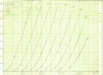
I enclose the triode mode curves for 6e5p, and one can see that at 275V 20mA working point, the grid voltage will be -5V relative to cathode voltage. With bypassed cathode resistor, you could be close to have 200v p-p plate voltage swing. Also you could estimate the internal Ri at this working point, I think it is higher than 1k.I will bypass second stage cathode resistor with 100uf MKP which I have a few.
Please tell me, are the voltages between tubes in my schematic correct? I've set second tube cathode voltage only 7V higher than first tube anode. I thought that 6,25VAC*32=200VAC of signal, so 7V will be about right to ensure 200V swing. Is this correct? Or should I change this value? What do You suggest?
As I can see, Ri=(420-235)V/95mA = 1k95
Attachments
Last edited:
I've also seen these curves but I couldn't find them right with what I have measured myself. Maybe I've done something wrong but for example Va=308 Vk=7,5 Rk=300 Ohm, so for about 300V I've got 25mA. For Va=302 Vk=7,3 Rk=270 Ohm so about 28mA and 8W of dissipation.
As for Ra, I've seen on Bartola's www some measurement with Va=79, Ia=20mA, Vg=-0,5V and Ra=960 Ohm. That is why I assume that Ra is around 1k. Ofcourse I could be wrong.
What do You think about using voltage divider between stages? If I assume right I could use 1:10 voltage divider and achieve about 10VDC when entering second tube grid. With 2Vac input I would have about 64VAC signal after first stage, so 1:10 it should be 6,4Vac right? Or this is only for DC calculation? Lowering second stage cathode voltage should yield in increase stability? Have You ever tried such abnormal configuration?
You shall have the first stage measured gain around 20, maybe less (load line slope and unbypassed cathode resistor). DAC output AC voltage usually 0,5...1V (2V will be from maybe one CD disk among 1000). By the input potentiometer, you could easily decrease it 10 times, so I do not see any need for additional interstage voltage divider.I've also seen these curves but I couldn't find them right with what I have measured myself. Maybe I've done something wrong but for example Va=308 Vk=7,5 Rk=300 Ohm, so for about 300V I've got 25mA. For Va=302 Vk=7,3 Rk=270 Ohm so about 28mA and 8W of dissipation.
As for Ra, I've seen on Bartola's www some measurement with Va=79, Ia=20mA, Vg=-0,5V and Ra=960 Ohm. That is why I assume that Ra is around 1k. Ofcourse I could be wrong.
What do You think about using voltage divider between stages? If I assume right I could use 1:10 voltage divider and achieve about 10VDC when entering second tube grid. With 2Vac input I would have about 64VAC signal after first stage, so 1:10 it should be 6,4Vac right? Or this is only for DC calculation? Lowering second stage cathode voltage should yield in increase stability? Have You ever tried such abnormal configuration?
Maximum input voltage for the second stage 3,5V AC (since grid bias is -5V only). With the second stage gain around 30 (bypass cap and choke load) you are close to what is needed.
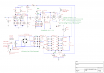
My parallel GM70 circuit.
Gain of the 6B4G is 3.75 (measured in circuit)
As attached: 1 volt RMS input gives 208V peak to peak
1.184Vrms input gives 244Vpp
This works very well as most modern equipment will put out 2Vrms
You could use a 2A3 instead of the 6B4G
Gain of the 6B4G is 3.75 (measured in circuit)
As attached: 1 volt RMS input gives 208V peak to peak
1.184Vrms input gives 244Vpp
This works very well as most modern equipment will put out 2Vrms
You could use a 2A3 instead of the 6B4G
Attachments
Doesn't seem like you can get 200V swing with only 95V on the plate of the driver. You might get that much swing with a different operating point for the 6E5. I agree with you about the sound of the 6E5. I have only some recent experience with them but really like them so far.
John
John
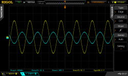
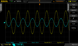
This moment I gave up dc coupling. I made something similar to my first schematic, but with cathode bypass capacitor as Vladimir suggested. It works to about 100V but after that sine gets distorted, what I saw even on my cheap pocket oscilometer. For now I've connected them with cap like this:
I've disconected 230Vac sine inverter so measurements on this image are done with normal fluctuating 225-245Vac from mains. Multimeter Uni-T UT61E, Fg-100 DDS function generator, DSO128 pocket oscilloscope with 10:1 probe. Wave set to 1kHz sine. To 200Vac sine is clear, I think above it also, but I can't measure it with my stuff. 6e5p in this configuration seems to be able to drive GM70 with plenty of swing. I will now this for sure when I finish whole amp.
Thank You Guys for the support. You were right that dc coupling is not so easy and safe as other ways of coupling stages. Thanks for 6B4G. I saw 6S4S is its russian equivalent so maybe I will give it a try someday.
Thanks again,
Daniel
An externally hosted image should be here but it was not working when we last tested it.
I've disconected 230Vac sine inverter so measurements on this image are done with normal fluctuating 225-245Vac from mains. Multimeter Uni-T UT61E, Fg-100 DDS function generator, DSO128 pocket oscilloscope with 10:1 probe. Wave set to 1kHz sine. To 200Vac sine is clear, I think above it also, but I can't measure it with my stuff. 6e5p in this configuration seems to be able to drive GM70 with plenty of swing. I will now this for sure when I finish whole amp.
Thank You Guys for the support. You were right that dc coupling is not so easy and safe as other ways of coupling stages. Thanks for 6B4G. I saw 6S4S is its russian equivalent so maybe I will give it a try someday.
Thanks again,
Daniel
Is it going to have enough swing to drive the GM70? I'm using the 12GN7A as a driver tube.
most of people know abut your amp ,are you happy with this driver tube ?
- Status
- This old topic is closed. If you want to reopen this topic, contact a moderator using the "Report Post" button.
- Home
- Amplifiers
- Tubes / Valves
- GM70 driver - dc coupled 6e5p stage