The screen current of 6P43P-E is actually very low and since the output stage is UL-connected, the risk of screen grid overload is much smaller than in case of pentode connection with fixed screen grid voltage.
I am not concerned about exceeding some design-center max. voltage ratings as long as the output stage topology is UL or triode and maximum plate dissipation is kept on sensible level.
These tubes used to work at much higher stress as frame output tubes of bw-tv.
I am not concerned about exceeding some design-center max. voltage ratings as long as the output stage topology is UL or triode and maximum plate dissipation is kept on sensible level.
These tubes used to work at much higher stress as frame output tubes of bw-tv.
I am not concerned about exceeding some design-center max. voltage ratings as long as the output stage topology is UL or triode and maximum plate dissipation is kept on sensible level.
These tubes used to work at much higher stress as frame output tubes of bw-tv.
Yes, in my youth I've cannibalized some old b/w TV's that had a PL84 (series heated equivalent to EL86) as the frame output tube, and I've seen the schematics of many more. But none of them exceeded the 200V Vg2 limit.
I have no concern about exceeding the plate voltage ratings to some extend (up to 350-400 V), as far as dissipation is kept well in it's limits, but due to my experiences a PL84 won't forgive exceeding the screen voltage ratings for a long time.
Best regards!
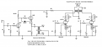
The 6P1P is forgiving, I've gotten almost 20W out of a pair in tetrode at 340V B+, 56ma bias.
In other news this stupid amp is built. There is too much gain, so I'm going to try about 6db NFB or converting the second stage to a cathode follower. I also need to finish turning the chassis into Swiss cheese, this thing runs hot but that's understandable seeing as plate+heater=240W!
Pics to come later today.

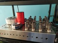
New pics. It's built and it sounds great. And because the tubes are cheap, the chassis was scrap, the power transformer and main cap were surplus, and the output transformers are power toroidals this build was under $150
Attachments
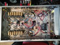

Sweet. Shouldn't have any problems with ventilation at least
")
What part number is the interstage you used? I might want to try some out at some point.
I'm sitting on a dozen 6V6 that are looking pretty good for a similar build... but I want to keep the sockets for the 6SN7 4x4 build I'm finalising... if I do it with 6V6 I have an excuse to order some more Antek toroids though...

Sweet. Any plans to add feedback, or do you like it as-is?
Oh, heres a handy trick I almost completely forgot- If anyone else is planning a similar project, go with the LM337 instead of the 317 if you haven't ordered any yet. It is the negative version of the 317, and will allow you to bolt the tab of the device directly to the negative rail, which is nice for being able to bus all the devices together to a single piece of heatsink or aluminum channel without worry of shorting them together, or needing to isolate them. Simply flip the diagram on its head and use the same resistor value as normal-
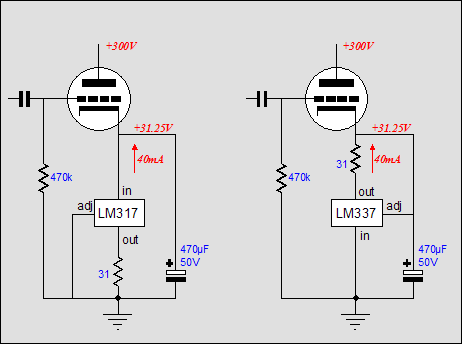
It's a neat little tweak that makes things a bit easier, and came in handy for some of my 6AS7G projects a while back. The only drawback really is that the 337 doesn't come in an "HV" version, so you need to mind the max voltage on them as you would running a regular 317.
Oh, heres a handy trick I almost completely forgot- If anyone else is planning a similar project, go with the LM337 instead of the 317 if you haven't ordered any yet. It is the negative version of the 317, and will allow you to bolt the tab of the device directly to the negative rail, which is nice for being able to bus all the devices together to a single piece of heatsink or aluminum channel without worry of shorting them together, or needing to isolate them. Simply flip the diagram on its head and use the same resistor value as normal-
It's a neat little tweak that makes things a bit easier, and came in handy for some of my 6AS7G projects a while back. The only drawback really is that the 337 doesn't come in an "HV" version, so you need to mind the max voltage on them as you would running a regular 317.
I like it as it is. I might experiment with NFB at a later time just to see how well it works through an interstage transformer.
Cheers for the info but according to these tests the LM337 performs far worse at high frequencies than the LM317. I just used those silicone insulators. For those needing more voltage the TL783 works at up to 125V.
EDIT: I see you read the latest Tubecad
http://waltjung.org/PDFs/Sources_101_P2.pdf
Cheers for the info but according to these tests the LM337 performs far worse at high frequencies than the LM317. I just used those silicone insulators. For those needing more voltage the TL783 works at up to 125V.
EDIT: I see you read the latest Tubecad
http://waltjung.org/PDFs/Sources_101_P2.pdf
Last edited:
Could a mod please change the name of the thread from "stupid" to "stupendous" as to more accurately describe this circuit?
I can't wait to do my parallel build now. I actually dug out most of my gear from storage, just looking for a suitable chassis
And the sound?Could a mod please change the name of the thread from "stupid" to "stupendous" as to more accurately describe this circuit?
- Home
- Amplifiers
- Tubes / Valves
- The "Stupendous" 6P1P 4PP amplifier!