It always seems (for power output) like a contradiction in terms. Constant current … but wait, it isn't is it? There is a bypass capacitor of 1,000 μF in parallel with each valve's “constant current” source. So essentially, it becomes “a smart resisistor”, programmable (by us, the designers) in the current domain, independent of the voltage drop. OK, now I'm happier.Nah, I'm not a CCS guy for output stages. It restricts you to class A unless you do some sort of state-variable bias current witchcraft.
Well, that bunch of words includes several I'm not familiar with.I'm leaning towards garter bias the most, 315 volts supply, 20+20 volts across ³⁹⁰R cathode resistors, mosfet screen supply (adjustable from 100-250 volts) sounds like it will work nicely.
Garter bias: Blumlein’s Garter Circuit Revisited seems like a good reference. Curious idea. Forcing the other tube (in a pair) to react to my cathode current flow. Cute.
20+20 volts across 390 Ω cathode resistors: now this took more head scratching. Mmm… maybe referring to… mmm… I don't know. A 390 Ω (single) cathode resistor might give what, 40 volts drop at 100 mA or so? That seems like a reasonable bias for the power tetrode. But maybe I'm missing something.
MOSFET screen supply, 100–250 V adjustable - “easy peasy”. Good choice too. Use that little LR₈N₃-G (450 V adjustable regulator) to generate the reference 100–250 V. Who knows, maybe toss in a shunt error-amplifier too. I'm coming to grips with the fact that the design is both simple and elegant, and offers an additional –20 dB or greater ripple reduction. Almost "for free".
Nah. KISS principle. The rest made sense. KISS…I was also considering fixed bias with mosfet source followers directly coupled to the output grids, AB2 should be killer with these tubes...
I worded things wrong I suppose...20+20 volts across 390 Ω cathode resistors: now this took more head scratching. Mmm… maybe referring to… mmm… I don't know. A 390 Ω (single) cathode resistor might give what, 40 volts drop at 100 mA or so? That seems like a reasonable bias for the power tetrode. But maybe I'm missing something.
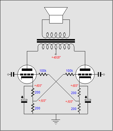
This circuit, with each of the four cathode resistors being 390R (and bigger grid leaks)
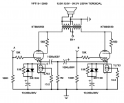
An externally hosted image should be here but it was not working when we last tested it.
At the chosen operating point, they should drop around ~20 volts or so.
I really like garter bias, it works super well, and is cheap and simple. It works well even with somewhat mismatched valves too, nice for cheap bulk-lot tubes
") I use it on my flea amplifier, and it has performed well for me long term in the past.
I use it on my flea amplifier, and it has performed well for me long term in the past.The mosfet filter is probably my new favorite circuit, and it's so versatile. This time around I've got five 51 volt Zeners as a reference, with a pot/resistor series connected across it for some nice adjustment. I thought about an error amplifier or reference IC of some sort, may be I'll try that soon. Next big project is a parallel sweep tube amp using parallel 12AV5GA, and that will definitely benefit from a more refined but still simple solution.
Last edited:
Then I must ask GoatGuy his take on the following? It's based on Broskies design without the Zeners (that just explode anyway).
Now that is a curious design. Using a back-to-back low VF 860 mV Schottky diodes to cut out the effect of the capacitors-in-parallel to the constant current adaptive voltage bias source during low signal conditions, then slewing the caps in or transients. Seems - just to me of course - like a pretty nonlinear response nexus. It isn't clear what Broskie was attempting. With or without the exploding Zeners.
Its also curious to see the 500 μF (total effective capacitance) from cathode-to-cathode. Truly floating, it is, with a bit of charging current thru that 1 MΩ to-ground resistor. Time constant of what, 1000 sec? Kind if ridiculous: would be better to use a 15 kΩ resistor (still 15 second RC) and get the big caps charged up in a reasonable amount of time. 15 kΩ also isn't egregiously loading, nor equally alarming local-negative-feedback extent. But that's just a value-tweak. 1 meg is fine, too.
GoatGuy
He was attempting class A with brief excursions into AB. See Cathode Bias with a Counstant Current Source
In the circuit, the SR1100 has a Vf of only 340mV. There isn't enough current to increase the Vf,
The 1M is because Broskie thinks polarized caps sound better with a polarizing voltage across them, and it costs 1 cent to implement.
In the circuit, the SR1100 has a Vf of only 340mV. There isn't enough current to increase the Vf,
The 1M is because Broskie thinks polarized caps sound better with a polarizing voltage across them, and it costs 1 cent to implement.
Last edited:
Ah. I=E/R → ²⁰/₃₉₀ → 51 mA. OK'…At the chosen operating point, they should drop around ~20 volts or so.
Yep. The MOSFET source follower is robust, simple, elegant, stabile, cheap, safe and readily available parts. I too consider it near the top-of-the-heap of solving all sorts of power supply objectives. I also like ''chains of Zeners'', especially when I have (as I do) 250 of them in various values. One of those grab-bags, how could you go wrong sort of deals. 250 for eight bucks. 10 ea in 25 values. Not stupid values, either. Pretty useful ones.The MOSFET filter is probably my new favorite circuit, and it's so versatile. This time around I've got five 51 volt Zeners as a reference, with a pot/resistor series connected across it for some nice adjustment. I thought about an error amplifier or reference IC of some sort...
Thanks for the schematic capture. It helps to know just exactly what we both are considering, balancing, talking about.
GoatGuy
I wouldn't argue against that last position. Aluminum oxide is a weird insulator: in the biased ("charged") direction, it is an excellent insulator nominally. However in the reverse direction, it acts as a preposterously ill-behaved semiconductor. Capacitors … used in passing A/C signal … of the electrolytic type, need to be charged up, to have any voltage swing(s) across them be entirely inside their Al₂O₃-as-insulator regime. Its good to see that Broskie agrees with that, even tho' we didn't exchange notes (LOL)He was attempting class A with brief excursions into AB. In the circuit, the SR1100 has a VF of only 340 mV. (GG: wow!) There isn't enough current to increase the VF beyond 340 mV, … The 1 MΩ is because Broskie thinks polarized caps sound better with a polarizing voltage across them.
GoatGuy
For post # 83, if one tube starts to run away, the other tube will too (and they will cause each other to run away faster).
(Positive Feedback Bias).
Be sure to use grid resistors that are no higher resistance than specified for the tube you use.
Since they are cross wired, it will likely need to be lower resistance than the normal self bias specification, i.e. if the maximum grid resistor for self bias is 200k Ohms, you may have to use something like 150k Ohms or 100k Ohms.
Last edited:
Just a quick informational update. I now have a power meter.
This amp as built uses 327W of power with a power factor of 0.7 for 15WPC It's my winter amp. I haven't used the heat in my apartment for 3 years.
I said it was stupendous, still it's one of the best sounding amps on Earth.
This amp as built uses 327W of power with a power factor of 0.7 for 15WPC
It's my winter amp. I haven't used the heat in my apartment for 3 years.I said it was stupendous, still it's one of the best sounding amps on Earth.
I calculated a loadline that seemed decent. a 6SN7 would work here, too.
Load Line Calculations – wauwatosa tube factory is a great resource to learn how to do it.
Load Line Calculations – wauwatosa tube factory is a great resource to learn how to do it.
O.K. I mean what operational point did you chose? Anode voltage, anode current, grid voltage etc.
Attached Svetlana's recommended values for different circuits with a 6N1P.
Attachments
Thanks!!280V B+, 3ma. 140V at the plate, 1.4V at the cathode I think...
ttached Svetlana's recommended values for different circuits with a 6N1P.
Thanks Artosalo!
Do you have something like that for 6P3S tube in triode mode??
- Home
- Amplifiers
- Tubes / Valves
- The "Stupendous" 6P1P 4PP amplifier!