Updated to show latest schematic. Boards are available if anyone else wants the best sounding 10 Watt class A triode output tube amp you can build for under 500$USD. When I built this, 6P1P were available for $1 each.

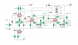
So the design uses a PPPP design meaning 8 6P1P per channel.
According to Push Pull Calculator the numbers look interesting.
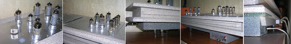
Since I have the parts laying around I thought I might build the following "stupendous" design. Stupendous in the sense that it's about 10% efficient.
In case it isn't clear, the 100k grid resistor is shared. In reality, if this sounds anything like it sims to spec, It's a contender to replace more expensive tubes such as 300b, providing electric power is cheap where you live. I'm fortunate enough to have my electricity included in my rent(!).
What do you all think of this?
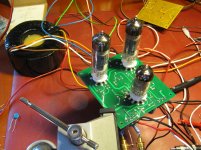
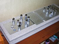
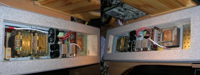
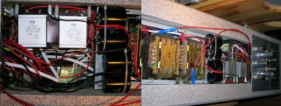
EDIT: I took a look inside of it after it's been on the shelf hooked up for a couple of years - better than expected... No bulding caps in the SMPS for the heaters")
Here's a shot of inside.

So the design uses a PPPP design meaning 8 6P1P per channel.
According to Push Pull Calculator the numbers look interesting.
Since I have the parts laying around I thought I might build the following "stupendous" design. Stupendous in the sense that it's about 10% efficient.
In case it isn't clear, the 100k grid resistor is shared. In reality, if this sounds anything like it sims to spec, It's a contender to replace more expensive tubes such as 300b, providing electric power is cheap where you live. I'm fortunate enough to have my electricity included in my rent(!).
What do you all think of this?
EDIT: I took a look inside of it after it's been on the shelf hooked up for a couple of years - better than expected... No bulding caps in the SMPS for the heaters
Here's a shot of inside.
Last edited:
Be careful. Matched tubes may not be matched at the operating point you use them at.
It is much more complex: but separate current sources, and separate bypass capacitors for each tube are suggested (or more easily, separate self bias resistors plus separate bypass capacitors for each tube). The resistors method will give easy measurement of the current in each tube, both when you start new, and when you have used the amp, i.e. for 6 months.
It is much more complex: but separate current sources, and separate bypass capacitors for each tube are suggested (or more easily, separate self bias resistors plus separate bypass capacitors for each tube). The resistors method will give easy measurement of the current in each tube, both when you start new, and when you have used the amp, i.e. for 6 months.
I know. But that's what I have. They aren't matched, and they don't need to be. The LM317s take care of that. They ARE all separate, one set for each tube. I guess it wasn't clear in the schematic. The real point of the CCSs is the idle current balance. From my experience these coils are VERY forgiving. I've seen a 10ma mismatch at sound levels that don't reveal it.
EDIT: If they seem to exceed the specs of the 50VA coil I'll upgrade them.
EDIT2: If it's built as shown using only one tube, you can connect the secondary in parallel instead of series for a nice ~3W.
EDIT: If they seem to exceed the specs of the 50VA coil I'll upgrade them.
EDIT2: If it's built as shown using only one tube, you can connect the secondary in parallel instead of series for a nice ~3W.
Last edited:
I would have just gone for a pair of more powerful output valves than use multiple pairs.
The 6P1P is a fantastic tetrode, and cheap! Basically a 6AQ5/6V6 in a 9-pin bottle. This gets you lots of transconductance (the total Gm will be the sum of the valves being paralleled) at lesser drive voltage than many of the big-boy tubes would require. This also allows for a lower turns ratio in the output transformer, lower copper losses, and often easier to design, also allowing the use of nice power toroidal types for those on a budget.
I love projects like this OP. Reminds me of a big, hot, nasty 5x5 parallel 6v6 triode build I did a few years ago. I fed the grids through an IRF820 source follower in fixed bias per side so I could reach deep into AB2 on high signal levels, and I used 200VA antek power toroids (i think 10volt output) for my output iron. It would go all the way down to 10hz without issues, and sounded fantastic. Efficiency be damned!
I've been thinking of doing something similar with the EL84/6P14P for the lower drive requirements at some point.
Could go full nutjob and run garter bias per each complimentary pair of devices, it would eat some of your supply voltage, but would ensure damn near perfect balance over time. I might do that for the parallel 6SN7 AB2 design I'm prototyping...
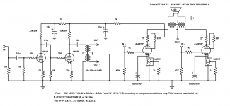
6P43P (EL86/6CW5) is very, very different type of tube than EL84.
It works best with essentially lower supply voltage (300 V) and load impedance. Some 5k is optimum as it is 8k for EL84.
With a pair of UL-connected 6P43P, 5k OPT and 300 V as +Ub, some 25 W is available.
As a triode and above parameters, some 11 W is available.
These are the results with actual amplifier, not simulations.
Attached the test circuit.
Attachments
Great information! I have a push pull 6P43P Triode connected amp running now but with a higher load (8-12k depending on speaker impedance) and it's a great sounding amp.
I have 16 6P43P in the mail, but I have the 6P1P now. Maybe I'll wait for them. I also have 6F12P.
What would the bias current be on your schematic?
I have 16 6P43P in the mail, but I have the 6P1P now. Maybe I'll wait for them. I also have 6F12P.
What would the bias current be on your schematic?
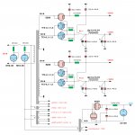
My PL84 PP amplifier with switching triode-pentode mode and thyratron rectifiers.6P43P (EL86/6CW5) is very, very different type of tube than EL84.
Attachments
-
 PL84_PP_LeCorbusier.jpg523.6 KB · Views: 1,532
 -
 PL84_PP_LeCorbusier_PSU.jpg945.6 KB · Views: 1,272
 -
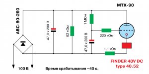 PL84_PP_LeCorbusier_Timer.jpg164.5 KB · Views: 1,074
 -
 DSCN7017.jpg547 KB · Views: 1,012
 -
 DSCN7021.jpg502.6 KB · Views: 947
 -
 Corbusier_1_2.jpg801.3 KB · Views: 499
 -
 Corbusier_1_4.jpg553.9 KB · Views: 436
 -
 Corbusier_6.jpg457.1 KB · Views: 394
 -
 Corbusier_7.jpg536.6 KB · Views: 509
Last edited:
What would the bias current be on your schematic?
40 mA / tube, measured at the cathode.
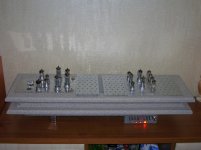
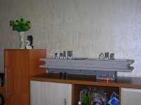
My PL84 PP amplifier..
Very massive. What is that brick ?
Last edited:
It is made from wood and painted with RUST OLEUMVery massive. What is that brick ?
Attachments
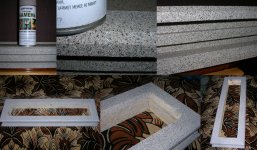
I'm glad of that your inpression, as it was just an idea to simulate the stone.And I thought that is was made of stone
The matter is in that my wife wanted the amp to be "unusually looking".
My PL84 PP amplifier with switching triode-pentode mode and thyratron rectifiers.
Nice use of a pentode for the "tail" up front
Interesting little design.
Ok I did some more math, and have updated the schematic.
Power supply to come but it's a 125V coil into a doubler. 470uf first caps, 470uf across them, 24R, 2200uf. PSUD gives 270mV ripple which should be ok for a PP output given the CMRR.
I'll build it tomorrow when I get some parts from Digikey.
Power supply to come but it's a 125V coil into a doubler. 470uf first caps, 470uf across them, 24R, 2200uf. PSUD gives 270mV ripple which should be ok for a PP output given the CMRR.
I'll build it tomorrow when I get some parts from Digikey.
Attachments
Having done a bunch of doublers the same way, I would split that resistor in half and move the other 470 between them, it'll give you a smidge more ripple reduction. Not that it would be a big deal either way though, since you are doing push pull outputs.
Come on man, you know you want to throw some feedback to the cathode of that 6N6P, and go pentode on the finals
All it would take is a bit more smoothing on a screen supply and a few components
Funny enough I'm drawing up a big (little) parallel push pull triode amp of my own, going to do eight 6H8C (russian 6SN7 for our friends in the audience) per channel (four bottles) in fixed bias with source followers for AB2 operation
I might even go full heretic and do it with a mosfet concertina splitter.
Hard to beat the brute elegance of a whole mess of triodes swinging like mad in perfect unison, mouths foaming and all
6P43P (EL86/6CW5) is very, very different type of tube than EL84.
It works best with essentially lower supply voltage (300 V) and load impedance. Some 5k is optimum as it is 8k for EL84.
With a pair of UL-connected 6P43P, 5k OPT and 300 V as +Ub, some 25 W is available.
As a triode and above parameters, some 11 W is available.
These are the results with actual amplifier, not simulations.
Attached the test circuit.
Being derivatives of the UL84, EL86's/6CW5's don't like to see more than 200 V at their screen grids. So, an UL amplifier fed off 300 Vdc might end in some major issues.
Otherwise you're quite right - these tubes are quite powerful, compared to the EL84/6BQ5.
Best regards!
- Home
- Amplifiers
- Tubes / Valves
- The "Stupendous" 6P1P 4PP amplifier!