Please let me know when I can pay.
When I make certain it works as expected. I wouldn't want to send you a defective set
")
Attachments

Last edited:
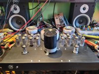
That looks like progress! Good luck.
I was thinking about the appeal of your PCB as a “Universal board”. May I suggest that you consider adding jumpers to separate the halves of the board, so that one could use the boards as originally intended in pairs, but also to just one board for a stereo PPP amp. And add what is needed to enable the use of the boards in triode, pentode and UL mode. I don’t know if it is feasible, but believe there could be interest in such a PCB.
I was thinking about the appeal of your PCB as a “Universal board”. May I suggest that you consider adding jumpers to separate the halves of the board, so that one could use the boards as originally intended in pairs, but also to just one board for a stereo PPP amp. And add what is needed to enable the use of the boards in triode, pentode and UL mode. I don’t know if it is feasible, but believe there could be interest in such a PCB.

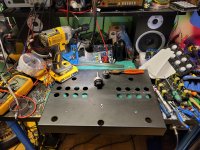
That moment when you realize you ran out of screws and now get to wait for them in the mail...
Are you making fun of my suggestion in post #190?
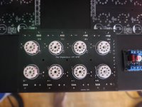
Nice, nice, nice. I'm too fuzzy this morning to go back to find your circuit diagram… but how close to the 12 W PA MAX are you running each of the 16 6Π1Π valves? Sigh… ⋅-=≡ GoatGuy ✓ ≡=-⋅
Using the double/tripler/quad board I made, 124V in give 320V out, and (480V or 640V (unloaded))
6P1P running 320V B+ /38mA a piece... (about 10W)
6F12P will do VA/PI with 480V and about 10mA each I think.
Are you making fun of my suggestion in post #190?
NO. I ran out of M3 screws that weren't too long or nylon. Using nylon anyway - they melt at 200°C so not worried.
As far as your idea of separating the halves into quarters, I can do that if you like...
Last edited:
Using the double/tripler/quad board I made, 124V in give 320V out, and (480V or 640V (unloaded))
6P1P running 320V B+ /38mA a piece… (about 10W)
6F12P will do VA/PI with 480V and about 10mA each I think.
Ah, got it. Looks like (https://frank.pocnet.net/sheets/113/6/6P1P.pdf) around –13.0 VDC on the grid as bias, or VKG thru capacitor bypassed CCS kathode biasing.
Also looks to be pretty near the top-recommended PA limit. But no matter!, that's what bottles do best. As an ol' wire-and-birch friend of me said, “if you're not red-plating, you're not having fun!”.
⋅-=≡ GoatGuy ✓ ≡=-⋅
- Home
- Amplifiers
- Tubes / Valves
- The "Stupendous" 6P1P 4PP amplifier!