Happy New Year!
Coming back to the design of tube-like hybrid amplifiers, one goal was to create an amplifier that has some desirable characteristics of all-tube amplifiers but optimizes away some undesirable aspects, frequently low "specific output" wrt. operating voltage, heat, weight, cost...
The approach outlined in this old thread was to "boost" a tube using solid state technology such that the tube characteristic dominates, ultimately arriving at the idea of current sharing between a tube and a feedback loop:
http://www.diyaudio.com/forums/tubes-valves/118725-hybrid-21.html#post2933421
But what if we construct an alternate view, centered on the output transformer?
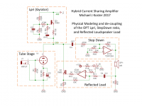
The circuit below contains the familiar chip-amp boosted tube stage, and goes another step to model it like a tube output transformer. I have separated the components to illustrate this.
The gyrator with extra B+ models the Primary Inductance (Lpri), allowing the tube to operate at a fixed DC point with high AC impedance.
The chip amp circuit models the step-down voltage ratio and current multiplication of the OPT, but multiplies the current by a very large factor. The tube only "sees" a high impedance resistive load.
The purpose of the Reflected Load is to set the current multiplication ratio of the modeled OPT to some desired value, putting some of the output load back on the tube. This can be set independently from the voltage ratio, allowing us to scale the tube down in current and voltage swing, while providing a scale model of the actual loudspeaker load for it to work into.
Some fraction of the AC current load at the output is reflected back to the plate circuit of the tube, to create a dynamic load impedance that looks more or less like what the tube would "see" through a transformer.
Some components are omitted to simplify the circuit...
Coming back to the design of tube-like hybrid amplifiers, one goal was to create an amplifier that has some desirable characteristics of all-tube amplifiers but optimizes away some undesirable aspects, frequently low "specific output" wrt. operating voltage, heat, weight, cost...
The approach outlined in this old thread was to "boost" a tube using solid state technology such that the tube characteristic dominates, ultimately arriving at the idea of current sharing between a tube and a feedback loop:
http://www.diyaudio.com/forums/tubes-valves/118725-hybrid-21.html#post2933421
But what if we construct an alternate view, centered on the output transformer?
The circuit below contains the familiar chip-amp boosted tube stage, and goes another step to model it like a tube output transformer. I have separated the components to illustrate this.
The gyrator with extra B+ models the Primary Inductance (Lpri), allowing the tube to operate at a fixed DC point with high AC impedance.
The chip amp circuit models the step-down voltage ratio and current multiplication of the OPT, but multiplies the current by a very large factor. The tube only "sees" a high impedance resistive load.
The purpose of the Reflected Load is to set the current multiplication ratio of the modeled OPT to some desired value, putting some of the output load back on the tube. This can be set independently from the voltage ratio, allowing us to scale the tube down in current and voltage swing, while providing a scale model of the actual loudspeaker load for it to work into.
Some fraction of the AC current load at the output is reflected back to the plate circuit of the tube, to create a dynamic load impedance that looks more or less like what the tube would "see" through a transformer.
Some components are omitted to simplify the circuit...
Attachments
Last edited:
Happy New Year Michael!
The three inversions around the N Feedback loop (IC1, IC2, Q1) should be nominally stable at low freq. Some gain roll-off likely needed at HF. Especially with inductance in the speaker.
The tube current and speaker current are in phase. So seems natural tube operation.
-----------------
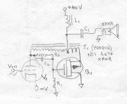
A possible simplification below using a Ferrite auto-xfmr (low turns, only Mosfet gate drive V signal handled within xfmr, teeter totter operation):
The current ratio should be close to the (inverse) turns ratio on the auto-former. Xfmr should be reasonably DC balanced, just AC gate drive voltage on it. (assuming the winding resistances are in similar proportion to the turns ratio.) (Option: could put a token resistance between the tube plate and its xfmr end, so the 1st order gate drive signal is automatically generated in the resistor without any teeter totter "V motion" required in the auto-xfmr. Auto-Xfmr only has to handle the "distortion" in the gate drive signal then, for really low turns )
Now to come up with a totem-pole P-P version...
The three inversions around the N Feedback loop (IC1, IC2, Q1) should be nominally stable at low freq. Some gain roll-off likely needed at HF. Especially with inductance in the speaker.
The tube current and speaker current are in phase. So seems natural tube operation.
-----------------
A possible simplification below using a Ferrite auto-xfmr (low turns, only Mosfet gate drive V signal handled within xfmr, teeter totter operation):
The current ratio should be close to the (inverse) turns ratio on the auto-former. Xfmr should be reasonably DC balanced, just AC gate drive voltage on it. (assuming the winding resistances are in similar proportion to the turns ratio.) (Option: could put a token resistance between the tube plate and its xfmr end, so the 1st order gate drive signal is automatically generated in the resistor without any teeter totter "V motion" required in the auto-xfmr. Auto-Xfmr only has to handle the "distortion" in the gate drive signal then, for really low turns )
Now to come up with a totem-pole P-P version...
Attachments
Last edited:
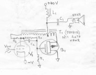
Fixed the simple version for ultra reduced xfmr turns:
N is turns ratio.
Rd provides 1st order linear gate drive signal for Q1, from V1 current across it.
Rd = N / gm_Q1
------------
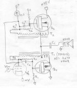
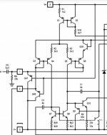
And a P-P version. Woops, a coupling cap or Zener needed between V1 plate and the top CCS to allow for the steady state gate drive DC offsets.
Some more work yet to eliminate C1
N is turns ratio.
Rd provides 1st order linear gate drive signal for Q1, from V1 current across it.
Rd = N / gm_Q1
------------
And a P-P version. Woops, a coupling cap or Zener needed between V1 plate and the top CCS to allow for the steady state gate drive DC offsets.
Some more work yet to eliminate C1
Attachments
Last edited:
Member
Joined 2009
Paid Member
Michael, I prefer simpler power gyrator topology like below. Loading of tube can be tailored by varying R2. A buffer with low 4H and above distortion to avoid buffer stage dominant spectra. I have not yet found any solution other than class A bias. Comments?
Attachments
Happy new year Michael;
glad to see you back!
Back in 2017 I designed a triode push-pul amp using 6S19P tubes, and QQE03/12 drivers. Positive feedback by current I took from cathode resistors of output tubes, and applied as a bootstrap to driver tubes. Such a way I killed 2 ducks by a single shot: increased damping factor, and added dynamic load to driver tubes without using any CCS or gyrators. ;-)
Michael, I prefer simpler power gyrator topology like below. Loading of tube can be tailored by varying R2. A buffer with low 4H and above distortion to avoid buffer stage dominant spectra. I have not yet found any solution other than class A bias. Comments?
Yes, there is definitely a huge circuit optimization to be had by modulating the gyrator element to produce the current feedback.
I like the ratiometric current mirror approach where a modulated current source drives a small current feedback signal to the gyrator, maybe around 1mA, which scales it up to the tube load current (10-20mA or more).
The big advantage using a modulated gyrator vs. the separate parallel anti-load is saving about 1/2 idle current in the output stage for the same tube operating conditions.
For push-pull topology and low quiescent current I am thinking class Ab (Big A, little b) with pentodes where each tube doesn't cut off but gets into the way low gm operating region. I also have a circuit design for a "Differential Gyrator" which works like the (idealized) coupled inductance of a tapped primary.
I will look into a modulated differential gyrator which may be able to present the scaled current feedback correctly to a push-pull pentode pair operating in asymmetric class A.
Note that the design using a parallel load can substitute an actual (iron and copper) choke for the gyrator.
PS since I am building mostly guitar amps now, and I have an immediate personal use for this, and discussion of instrument amps is not allowed on this list, I will probably take up this discussion over on the instruments and amps board.
Last edited:
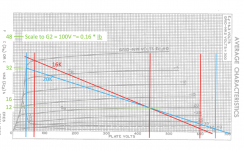
Scaled bigA, little b, asymmetric pentode load line
Here is a 6L6GC scaled down to 100V G2 to illustrate the idea of a push-pull output stage operating point, using this basic idea. We don't need to be a aggressive in biasing toward cutoff because we're operating at 12mA due to the scaled down Vg2 and scaled up load impedance.
I guess for push-pull, the current feedback can be inverse polarity and on the opposite side..
Attachments
Last edited:
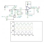
Floating Interactive Current Multiplier
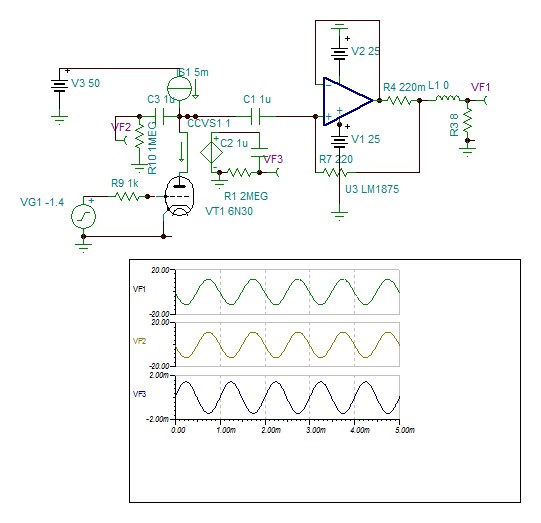
The power opamp multiplies by 1000 the input current, reflecting the tube 8k ohms load. The load sees the impedance of the tube 1000 times lower 2.76 ohms. The multiplying ratio is R7/R4+1.
Hayk
The power opamp multiplies by 1000 the input current, reflecting the tube 8k ohms load. The load sees the impedance of the tube 1000 times lower 2.76 ohms. The multiplying ratio is R7/R4+1.
Hayk
Attachments
Last edited:
Hi Indra. What makes you think as such. The datasheet doesn't speak anything particular about it. The circuit diagram shows diodes on each input constraining the inputs to the rails as well a limiting diode between the inputs.
I have a personal question. I stayed in Bogor about a month in 2001 studying about tropical trees in the botanical garden. Near the entrance was a market place, where on the walkway, along with vegetable vendors, was a young man about 16/17 years old assembling power amplifiers 3055/2955 base from a to z and selling them like pancakes. Every morning as I greeted him, made me feel so tiny. Do you know him?
I have a personal question. I stayed in Bogor about a month in 2001 studying about tropical trees in the botanical garden. Near the entrance was a market place, where on the walkway, along with vegetable vendors, was a young man about 16/17 years old assembling power amplifiers 3055/2955 base from a to z and selling them like pancakes. Every morning as I greeted him, made me feel so tiny. Do you know him?
Attachments
Hi, with max supply at +- 30V and stability at gain >10, there was little need for the inputs to handle > 3V swing. Of course the real limit needs to be tested, but no surprise if distortion starts to jump at a relatively low voltage swing at the inputs. Perhaps it is more rewarding to bootstrap an op amp driving a follower, then add the current multiplier and other desired enhancements.
Sorry, I do not know the young man you mentioned, from late 90s to about a couple years ago I was mostly in Jakarta.
Sorry, I do not know the young man you mentioned, from late 90s to about a couple years ago I was mostly in Jakarta.
Attachments
Indeed most opamps distort when reach rail voltages to see if the dropout 4v is sufficient to maintain the input transistors biased . The Michaels purpose is to reflect the output and plate impedances to each other so that the speaker sees the nonlinear character of the plate and the plate sees the reactive and resistive elements of the speaker. By this you can use a small triode and make it resemble to a high power SET, ingenious idea, Thank you Michael.
Lm1875 is not unity gain stable
Av greater then 10 to be stable.
More discussion about stability is taking place here How to parallel multiple power amps?
- Status
- This old topic is closed. If you want to reopen this topic, contact a moderator using the "Report Post" button.
- Home
- Amplifiers
- Tubes / Valves
- A new perspective on current-sharing hybrid amplifiers