Hi,
The datasheet of 6by5 damper tube listed 175ma per diode. In a fullwave hybrid bridge rectification, each 6by5 will only pass current 50% of the time, does it mean the output current cab be double to 350mA?
I see that Thomas Mayer of VinylSavor uses 6by5 for stereo 6cb5a SE amp at fullwave 425v/200ma (VinylSavor: Single Ended Amplifier Concept, Part 3).
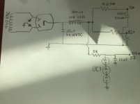
I'm planning to use it for choke input purposes with output 450V/180mA. Power trans secondary is 540v/300ma. Please advise if 6by5 can be used.
The datasheet of 6by5 damper tube listed 175ma per diode. In a fullwave hybrid bridge rectification, each 6by5 will only pass current 50% of the time, does it mean the output current cab be double to 350mA?
I see that Thomas Mayer of VinylSavor uses 6by5 for stereo 6cb5a SE amp at fullwave 425v/200ma (VinylSavor: Single Ended Amplifier Concept, Part 3).
I'm planning to use it for choke input purposes with output 450V/180mA. Power trans secondary is 540v/300ma. Please advise if 6by5 can be used.
Yes, you can pull 350 mA. from your hybrid bridge, perhaps a little more. Damper diodes, like the 6BY5, are rated for high pulse currents and have a 50% duty cycle in a bridge.
You should be fine with the hybrid bridge. The power trafo will run cool, as you can access the full VA rating, when choke I/P filtration is employed. Protect the SS diodes in the bridge from inductive kick back spikes by installing a 0.01 μF. ceramic cap. of the highest WVDC you can source in what would be the 1st position of a CLC filter.
You should be fine with the hybrid bridge. The power trafo will run cool, as you can access the full VA rating, when choke I/P filtration is employed. Protect the SS diodes in the bridge from inductive kick back spikes by installing a 0.01 μF. ceramic cap. of the highest WVDC you can source in what would be the 1st position of a CLC filter.
Thanks Eli, you are most helpful. I will be using a 0.22uf 1000v PIO Westcap as C1.
Any idea what's the warm up time for 6by5? Heard dampers have a slow warm up advantages but not sure if it applies to all. I will not be using a heavy bleeder resistor therefore slow warmup will prevent voltage ramp up before power tube warm up.
Any idea what's the warm up time for 6by5? Heard dampers have a slow warm up advantages but not sure if it applies to all. I will not be using a heavy bleeder resistor therefore slow warmup will prevent voltage ramp up before power tube warm up.
I will be using a 0.22uf 1000v PIO Westcap as C1.
That's too much capacitance and the WVDC is way too low. This is the sort of part needed to deal with inductive kick back spikes.
The inductive kick back spikes are huge, way more than the RMS value times 21/2.
A 0.1 μF. part makes the filter pseudo-choke I/P and the rail voltage will be greater than approx. 0.9 times the RMS value, less losses. A 0.68 μF. part is big enough to incur the risk of making the filter cap. I/P, with very poor rail voltage regulation.
The 1st inductor in a choke I/P filter has to be rated for that duty. A part in that position is subjected to great strain. If a choke not specifically rated for critical current service is to be employed in that role, its current handling capability must be derated, perhaps by as much 50%.
Something like this might be better suited, as Eli says. At least you know it'll probably outlive the power supply it's installed in.
0.1uF 4kV Polyester Film Capacitor Siemens MKT B32227 | eBay
0.1uF 4kV Polyester Film Capacitor Siemens MKT B32227 | eBay
Hi Eli or whomever for that matter. What size cap can you add after the choke input filter? Do the same cap size restrictions matter after the choke input?
I’m doing the exact supply mentioned above coincidentally and don’t want to oversize the capacitors after the 10H choke.
Thanks!
I’m doing the exact supply mentioned above coincidentally and don’t want to oversize the capacitors after the 10H choke.
Thanks!
A reasonably large valued 'lytic is fine after the I/P choke. Remember, older versions of the ARRL handbook strongly suggest the use of LCLC topology. With a good sized 1st filter cap., the 2nd inductor need not be large valued. Also, a "routine" choke is just fine in the 2nd position.
If your signal tubes don't draw the critical current place a high wattage 10 Kohm bleeder resistor across the 1st filter capacitor. A reasonable approximation for the critical current, in mA., is V/L. The approximation works out to 1000 Ω/henry. Notice that larger 1st inductances require smaller critical currents.
If your signal tubes don't draw the critical current place a high wattage 10 Kohm bleeder resistor across the 1st filter capacitor. A reasonable approximation for the critical current, in mA., is V/L. The approximation works out to 1000 Ω/henry. Notice that larger 1st inductances require smaller critical currents.
Hi Eli,
I’m using a Hammond 193Q in the I/P position and really am constrained for space to add another choke, so I planned on possibly using a CRC following the choke. I would think the ripple would be fairly low off the choke already. I can load it with a 10K resistor. Should I feed my plates after the choke or after the CRC after the choke? Will the regulation be the same off the CRC as directly after the choke?
Thanks!
Make the 1st filter cap. big. There's plenty of ripple to suppress, after the I/P choke. Let's go for check valve channel to channel isolation. Use a pair of UF4007s and 15 Ω resistors wired in series (1 pair/channel) feeding separate reservoir capacitors. Losses in the 15 Ω resistors will be tolerable, while ripple suppression will be decent.
Hi
With all due respect to Eli (whom I respect greatly and has helped me and others out many times)
Inductive kick-back happens most often when the load is removed. The potential energy in the input choke is still there, and manifests itself as a huge voltage, unless it is has an easy way to dissipate.
So, I typically just bypass my first filter capacitor with some kind of 2watt or higher 100k Ohm resistor.
6by5 is ok for medium current demands, But I go to a nice pair of 6AU4 or 6AX4 etc. for power amps.
ah. good observation. True that 6AX4 has lower max current. however it has much higher peak inverse plate voltage rating than the 6BY5
So I am a bit more careful with 6BY5, especially regarding current and especially the size of that 1st choke.
Since I started bypassing the 1st cap (with i.e. 100k Ohm resistor) after the choke I didn't see a 6BY5 dying. I did have a few die some years ago, but they came from a lot that was not stored so well (in the "open" for a few years perhaps). This is just my experience mind you. I never had SS 1n4007 diodes die though. And I never had any problem with 6AX4 or 6AU4 diodes, etc. - these dampers were built to last. There are other great ones out there too. - some noval bases.
So I am cautious with 6BY5 - I would always advise to use Duncan amps PSU-II to simulate your circuit in advance as well. That lower PIV rating might not always work out so well.
Last edited:
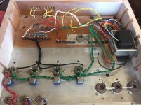
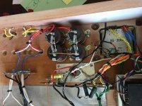
Thanks! You think the series resistance on my caps in this picture are enough to not have the need for additional resistance from B+ to ground? Each leg has 200K on it or two 100K in series across the caps.
That should be fine from my experience. Of course Eli has much MORE experience than me, so the choice is yours. His little ceramic cap is certainly not expensive (I just never tried it). Did you try to simulate your circuit with PSUD-II ? You will need to download the separate rectifiers file (which has more in it than what is normally available) to simulate 6BY5.
BTW - In your schematic you need a capacitor after that 1st choke but I assume these are what is in your picture.
After rectification with choke input, and 180mA draw, I am seeing a B+ around 350V in PSUD-II. I don't have specs on your power transformer this is sort of a rough estimate.
Last edited:
- Status
- This old topic is closed. If you want to reopen this topic, contact a moderator using the "Report Post" button.
- Home
- Amplifiers
- Tubes / Valves
- 6by5 hybrid bridge